Fault tolerant network utilizing bi-directional point-to-point communications links between nodes

a communication link and fault-tolerant technology, applied in the field of data communication system, can solve the problems of jitter on the local network clock, significant cost, and the effect of flexray protocol achievemen

Active Publication Date: 2012-05-15
LUTRON TECH CO LLC
View PDF69 Cites 186 Cited by
  • Summary
  • Abstract
  • Description
  • Claims
  • Application Information

AI Technical Summary

Benefits of technology

[0019]The present invention provides a fault tolerant network capable of supporting the existing applications serviced by MOST and CAN and the new applications of X-by-wire targeted by FlexRay without the prohibitive cost of duplicate cabling, which includes both the wiring and any necessary hubs or stars.
[0020]An improved data communication system in accordance with the present invention preferably uses single-channel bi-directional point-to-point links between nodes to send frames of data. The network nodes can be connected together in a ring or daisy chain topology with successive data frames sent in alternating directions through the bi-directional links. A network that is initially configured as a ring can re-configure to a daisy chain when a communication link or network node fails. Nodes adjacent to a faulty link or node can determine that a failure exists and trigger the network to re-configure. When the failing link or node recovers, the network can detect the change and revert back to the ring configuration.
[0021]When implemented with a digital phase locked loop (DPLL) for clock recovery, all nodes can operate synchronously to each other as in SONET and MOST, which eliminates the need for special “clock synchronization calculation schedules” as in FlexRay. The jitter on the local clocks synchronized to the network is similar to MOST and substantially lower than for FlexRay, which is advantageous for real time streaming applications such as audio and video.
[0027]The improved system makes use of the concept of sending data frames in opposite directions around a ring or through a daisy chain. Protocols such as SONET, Token Ring, FDDI, and MOST use a ring topology, however, data always travels in one direction through the interconnect. This is because unidirectional communication channels are simpler to build. Each node has a dedicated transmitter and a dedicated receiver, instead of two transceivers. In the case of optical interconnect, a transmitter typically uses an LED and a receiver uses a silicon photodiode, but cost effective optical transceivers may utilize a single LED for both transmit and receive, which helps provide for cost effective implementations using optical interconnect.

Problems solved by technology

The FlexRay protocol achieves these requirements, but at significant cost, since redundant cabling provides the fault tolerance.
All other nodes have free running clocks that are periodically synchronized to the timing reference, which results in some jitter on the local network clocks.
FlexRay was developed for X-by-wire applications since other automotive networks such as CAN and MOST did not fulfill the necessary requirements for bandwidth and deterministic behavior (in the case of CAN), and fault tolerance (in the case of MOST).
CAN is not appropriate for X-by-wire applications since the data rate is too low, less than 1 Mbit / sec, and there are no dedicated timeslots for high priority communication.
Although MOST has plenty of bandwidth for X-by-wire applications and has the dedicated timeslots that provide guaranteed bandwidth, FlexRay was developed primarily because MOST did not provide fault tolerance at the time.
Just like with SONET, MOST could provide single point fault tolerance with a redundant communication channel traveling in the opposite direction of the main ring, however, like FlexRay, this doubles the cost of the physical layer.

Method used


Image

  • Fault tolerant network utilizing bi-directional point-to-point communications links between nodes
  • Fault tolerant network utilizing bi-directional point-to-point communications links between nodes
  • Fault tolerant network utilizing bi-directional point-to-point communications links between nodes

Examples


Embodiment Construction

)

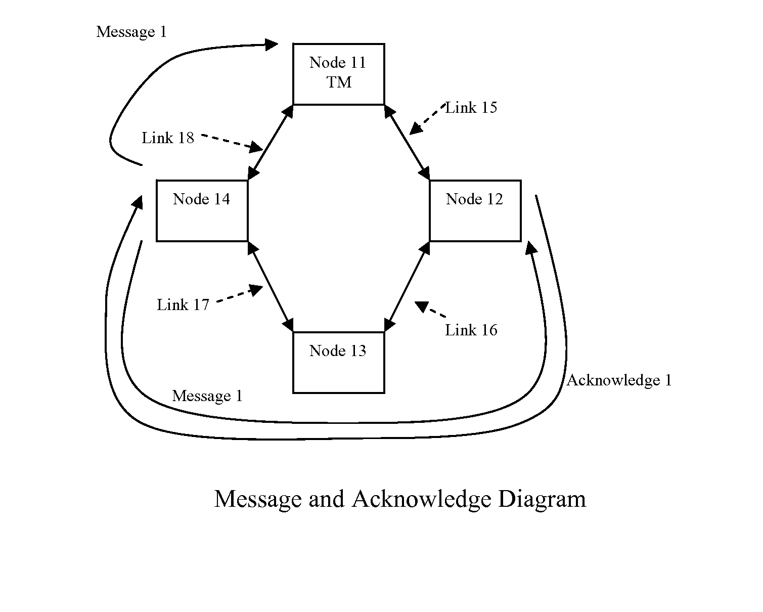
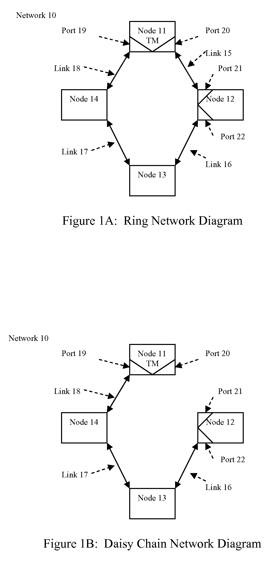
[0053]Turning now to the drawings, FIG. 1A illustrates a group of nodes 11, 12, 13, and 14 connected in a ring topology by communication links 15, 16, 17, and 18. Each node has at least two ports illustrated by ports 19 and 20 on node 11 and ports 21 and 22 on node 12, which can communicate data in both directions. Node 11 in this example is defined as the timing master (TM), which repetitively sends a data frame around the ring in alternating directions. A first data frame travels from port 20 clockwise around the ring to port 19. After the complete data frame is received at port 19, the next data frame is sent from port 19 counter clockwise around the ring to port 20. Successive data frames continue alternating in direction, which allows all nodes to communicate with each other. The communication links preferably use plastic optical fiber (POF), but could use a wide variety of communication media including twisted pair wire or coaxial cable for instance.

[0054]FIG. 1B illustrates ...


PUM


Abstract

A data communication system and an associated network node implementation is disclosed that, in certain embodiments, uses single-channel bi-directional communication links between nodes to send frames of data. The network nodes can be connected together in a ring or daisy chain topology with data frames sent in alternating directions through the bi-directional links. Such networks initially configured in a physical ring topology can tolerate single point failures by automatically switching to a logical daisy chain topology.

Description

BACKGROUND[0001]1. Field of the Invention[0002]This invention relates to a data communication system that preferably uses bi-directional communication links between network nodes to send frames of data.[0003]2. Description of the Related Art[0004]Modern data communication networking can be traced back to at least the late 1950s and early 1960s with the introduction of the Telecommunication carrier or T-carrier system by Bell Labs for communicating digitized voice streams around the world. The personal computer revolution triggered the introduction of a variety of computer network technologies, including ARCNET, Token Ring, Ethernet, and FDDI, in the late 1970s and early 1980s, with Ethernet becoming the dominate computer networking protocol over time. As the demand for wide area data communication grew, the telecommunications industry responded in the late 1980s and early 1990s with the introduction of technologies such SONET to carry the ever growing data traffic along with the tra...

Claims


Application Information

Patent Timeline
Patent Type & Authority Patents(United States)
IPC IPC(8): G01R31/08H04L12/28H04L45/28
CPCH04L12/43H04L12/437H04L45/28H04L2012/40273
Inventor KNAPP, DAVID J.
Owner LUTRON TECH CO LLC
Why Eureka
Try Eureka