Explosive decompression propulsion system

a propulsion system and explosion technology, applied in the direction of printing, white arms/cold weapons, weapons, etc., can solve the problems of high cost, dangerous explosions, and use of non-renewable resources, and achieve the effect of high velocity and for

Inactive Publication Date: 2012-05-22
CAUSWAVE
View PDF116 Cites 18 Cited by
  • Summary
  • Abstract
  • Description
  • Claims
  • Application Information

AI Technical Summary

Problems solved by technology

Currently, projectile systems require combustible fuels which explode to propel an object.
Such systems pollute the environment, use non-renewable resources, create dangerous explosions, and are expensive.

Method used


Image

  • Explosive decompression propulsion system
  • Explosive decompression propulsion system
  • Explosive decompression propulsion system

Examples


Embodiment Construction

in conjunction with the accompanying figures.

BRIEF DESCRIPTION OF THE DRAWINGS

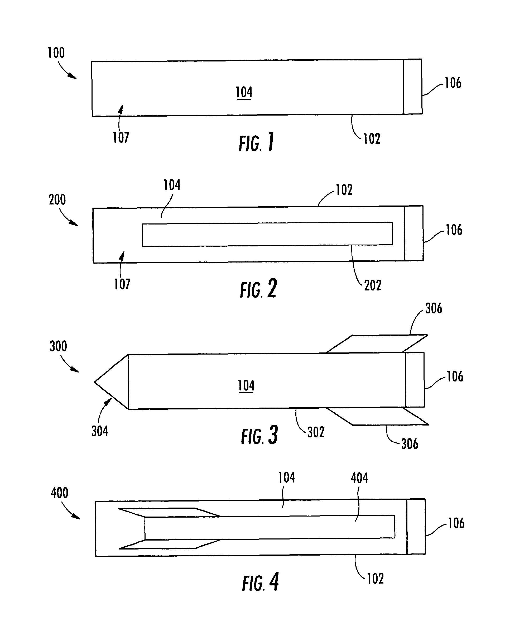
[0007]FIG. 1 is a projectile propulsion system in accordance with an embodiment of the present invention.

[0008]FIG. 2 is a projectile propulsion system in accordance with another embodiment of the present invention.

[0009]FIG. 3 is a projectile propulsion system in accordance with another embodiment of the present invention.

[0010]FIG. 4 is a projectile propulsion system in accordance with another embodiment of the present invention.

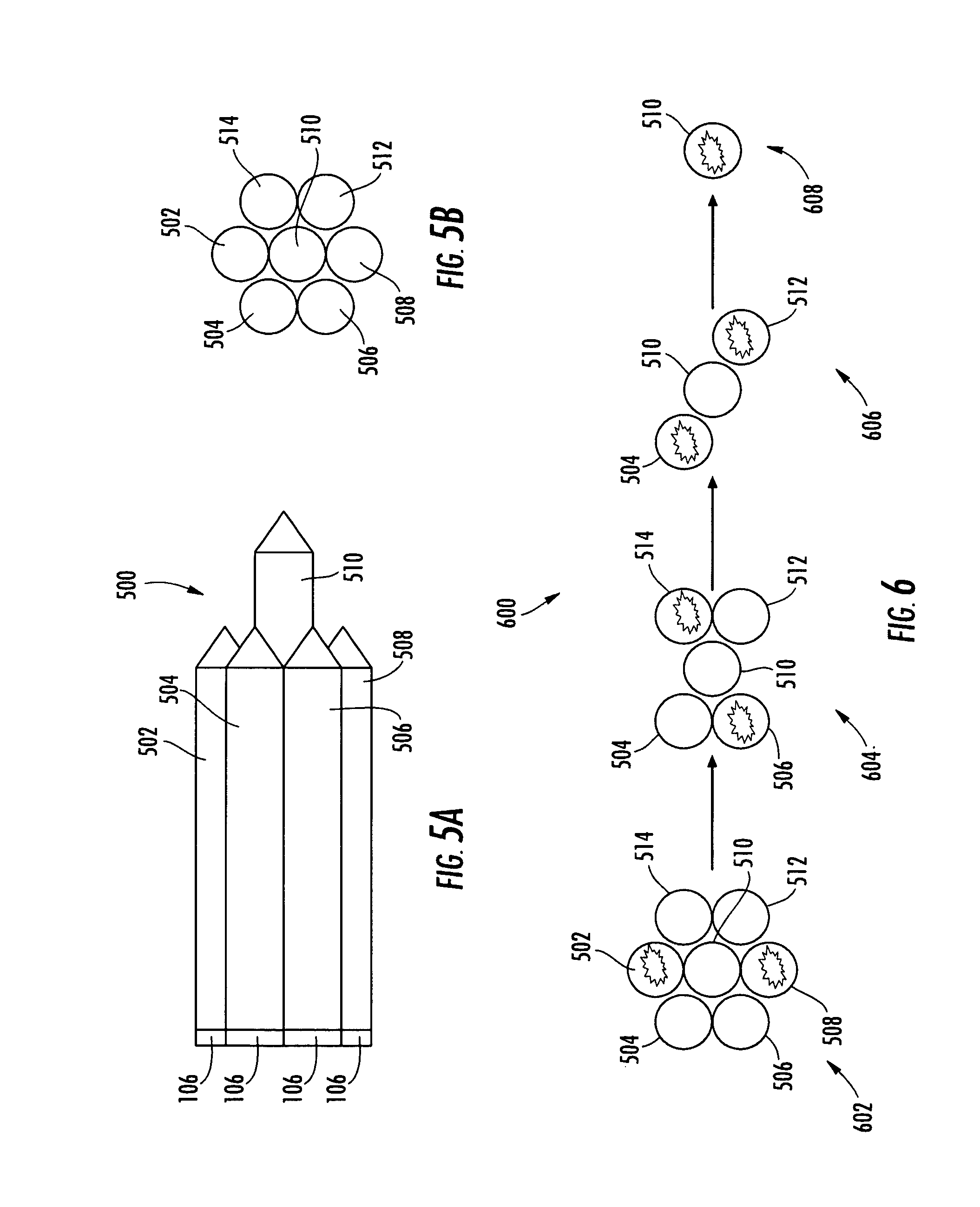
[0011]FIGS. 5A-B (collectively FIG. 5) is a multistage projectile propulsion system in accordance with another embodiment of the present invention.

[0012]FIG. 6 illustrates a method of operation of the multistage projectile propulsion system of FIG. 5 in accordance with an embodiment of the present invention.

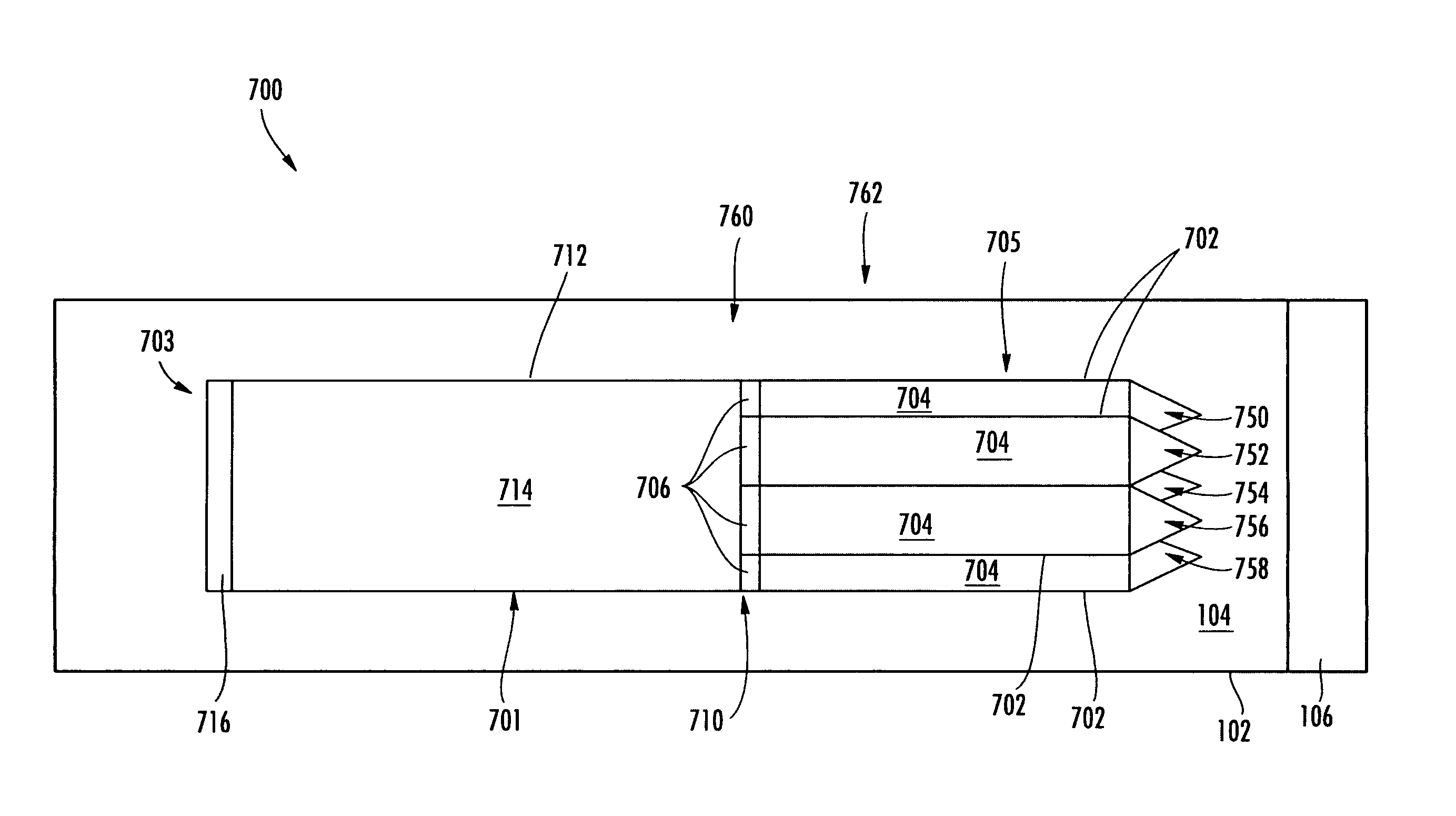
[0013]FIG. 7 is a multistage projectile propulsion system in accordance with another embodiment of the present invention.

[0014]FIG. 8 is a block schematic diagram of an exampl...


PUM

PropertyMeasurementUnit
pressureaaaaaaaaaa
pressureaaaaaaaaaa
velocityaaaaaaaaaa

Abstract

A projectile propulsion system includes a launch tube, multiphase material, and a membrane. The launch tube has an interior cavity, the multiphase material disposed therein. The launch tube also has an opening to receive the multiphase material. The membrane seals the opening while the multiphase material is disposed in the interior cavity of the launch tube so as to allow the launch tube to be pressurized. When the membrane is broken, a supersonic wave thrusts the contents of the interior cavity, such as a projectile, outwards with a high velocity and force.

Description

CROSS-REFERENCE TO RELATED APPLICATION[0001]This application claims priority from provisional patent application having Ser. No. 61 / 130,547 and filed Jun. 2, 2008, the entire disclosure of which is incorporated herein by reference.BACKGROUND OF THE INVENTION[0002]Currently, projectile systems require combustible fuels which explode to propel an object. Such systems pollute the environment, use non-renewable resources, create dangerous explosions, and are expensive.[0003]There is a need to create a projectile propulsion system.SUMMARY[0004]In accordance with an aspect of the present invention, a projectile propulsion system includes a launch tube, multiphase material, and a membrane. The launch tube has an interior cavity, the multiphase material disposed therein. The launch tube also has an opening to receive the multiphase material. The membrane seals the opening while the multiphase material is disposed in the interior cavity of the launch tube so as to allow the launch tube to be...

Claims


Application Information

Patent Timeline
Patent Type & Authority Patents(United States)
IPC IPC(8): F41F3/04
CPCF41B11/68F41F1/00F41A1/04F42B5/02Y10T29/49346
Inventor RIGGS, JEFFREY L.OLEYNIK, VLADISLAVBOROVIKOV, VALERYALBUL, GENNADIY
Owner CAUSWAVE
Why Eureka
Try Eureka