Reinforced stabilising strip intended for use in reinforced earth structures

Active Publication Date: 2012-05-22
TERRE ARMEE INT
View PDF16 Cites 3 Cited by
  • Summary
  • Abstract
  • Description
  • Claims
  • Application Information

AI Technical Summary

Benefits of technology

[0018]Advantageously, the cord has high tensile strength and increases the internal cohesion between the fibres. In addition, the arrang

Problems solved by technology

Such an arrangement of the fibres poses the risk of sliding between fibres and between a group of fibres and the strip,

Method used


Image

  • Reinforced stabilising strip intended for use in reinforced earth structures
  • Reinforced stabilising strip intended for use in reinforced earth structures
  • Reinforced stabilising strip intended for use in reinforced earth structures

Examples


Embodiment Construction

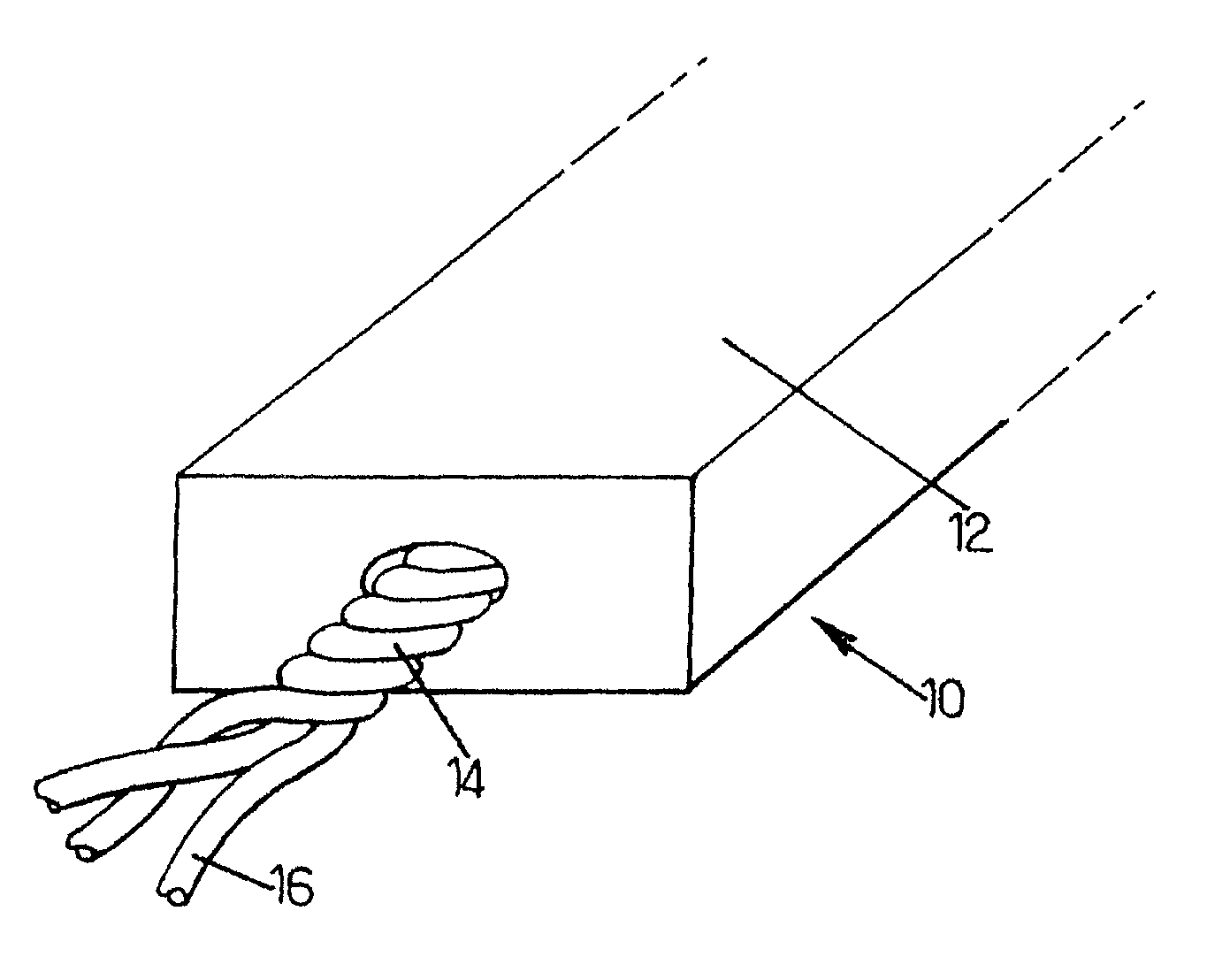
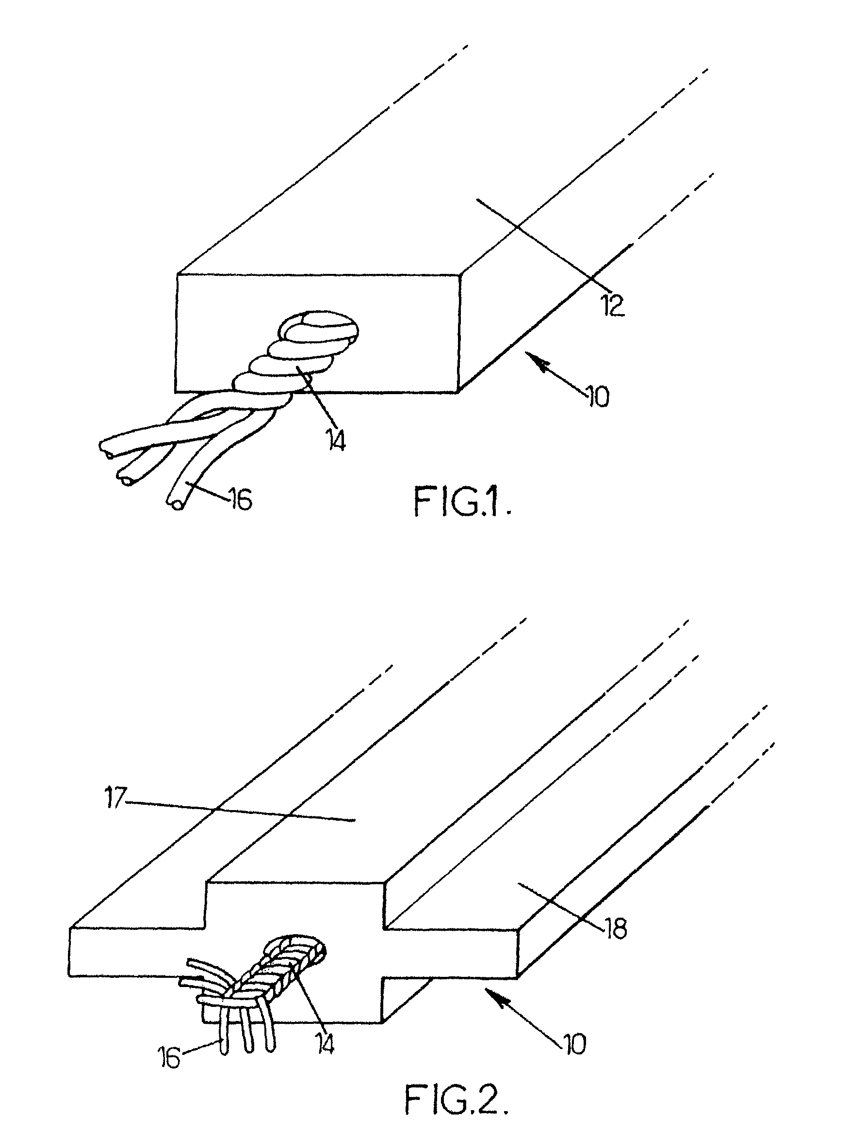
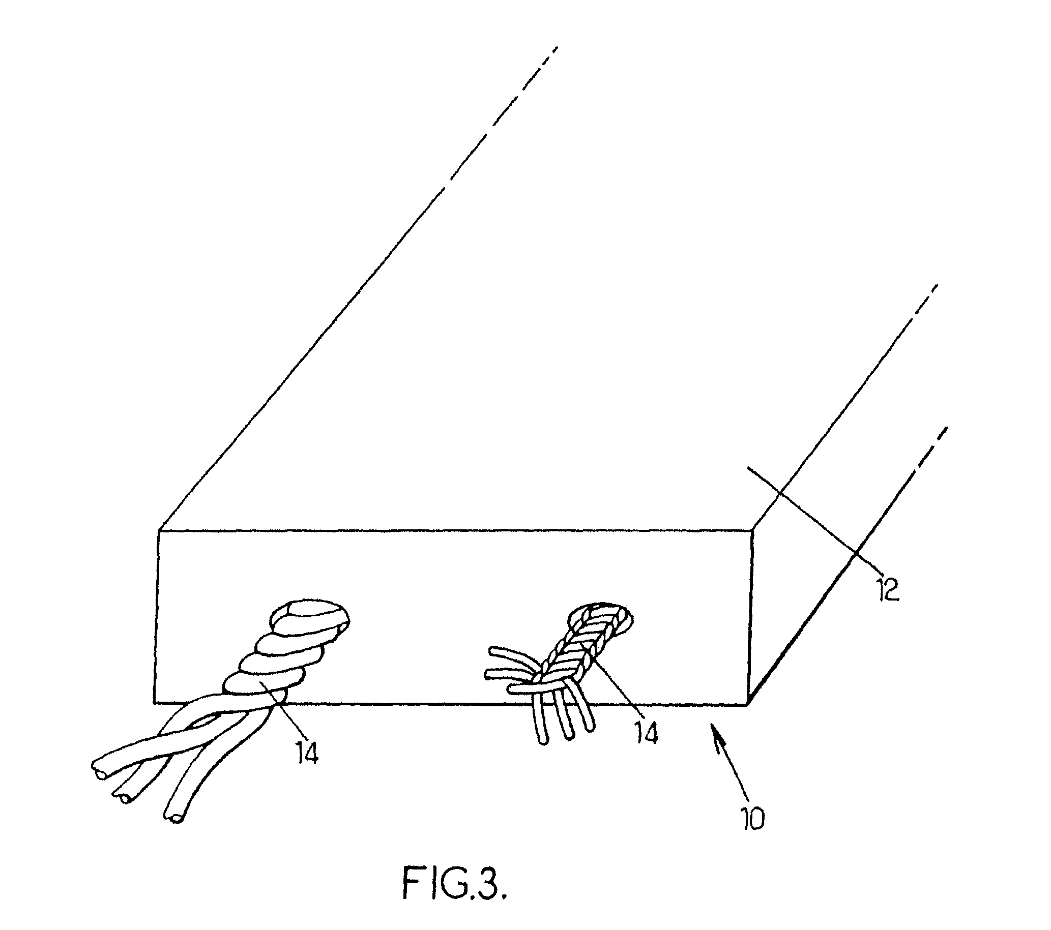
[0037]In the sense of the invention, “cord” is given to mean an assembly, for example obtained by twisting or braiding, of at least three fibres made up of a plurality of strands of yarn or directly of at least three strands of yarn, made from textile, synthetic, plastic or metal materials or a combination of these different fibres or yarns. It is known to a person skilled in the art that the at least three fibres making up a cord are assembled in such a way as to form a stable construction.

[0038]The yarns in the sense of the invention are made up of a group of monofilaments and / or discontinuous fibres and / or fibrillated yarn assembled and twined.

[0039]A cord according to the invention can comprise at least three strands, each strand being made up of a plurality of fibres assembled in such a way as to form a stable construction.

[0040]A cord according to the invention can be a plaited cord in the sense of standard NF EN ISO 1968, namely obtained by braiding together strands to form a...


PUM


Abstract

Reinforced stabilizing strip (10) intended for use in reinforced earth structures, comprising a longitudinal part (12), said longitudinal part (12) comprising along at least part of its length, at least one cord (14) arranged approximately longitudinally and encased in the bulk of said longitudinal part.

Description

BACKGROUND OF THE INVENTION[0001]1. Field of Invention[0002]This invention relates to a reinforced stabilising strip intended for use in reinforced earth or strengthened soil structures, together with the use of such a strip for the construction of reinforced earth or strengthened soil structures.[0003]2. Description of the Prior Art[0004]A reinforced earth structure combines compacted backfill, a facing and reinforcements that are connected or not to the facing.[0005]Various types of reinforcement can be used: metal, for example galvanised steel, or stabilising strips, for example polyester fibre-based. They are placed in the earth at a density that depends on the stresses that are likely to be exerted on the structure, with the thrust stress of the ground being taken up by the friction between the earth and the reinforcements.[0006]The facing is usually made from precast concrete elements in the form of slabs or blocks, juxtaposed to cover the front surface of the structure.[0007]...

Claims


Application Information

Patent Timeline
IPC IPC(8): E02D29/02
CPCE02D29/0241E02D17/202
Inventor MORIZOT, JEAN-CLAUDEFREITAG, NICHOLAS
Owner TERRE ARMEE INT
Why Eureka
Try Eureka