Vertebral body replacement device and method for use to maintain a space between two vertebral bodies within a spine

a technology of vertebral body and spine, which is applied in the field of orthopaedic and neurosurgical implants, can solve the problems of permanent damage to the spinal cord, improper neck and back alignment, and neurologic impairment, and achieve the effect of improving the implanted vertebral space, lengthening and shortening the devi

Active Publication Date: 2012-05-22
AESCULAP IMPLANT SYST
View PDF218 Cites 41 Cited by
  • Summary
  • Abstract
  • Description
  • Claims
  • Application Information

AI Technical Summary

Benefits of technology

[0005]Advancement of the state of spinal implants and the surgical management relating to the clinical presentation of missing or damaged vertebral bodies within an intact spinal column is believed desirable. The present invention satisfies the need for improvements to the vertebral space implant used to treat patients suffering from either diseased or damaged vertebral bodies by providing an in vivo adjustable vertebral body replacement device for use within a spinal column that eliminates torsional forces being applied at the implant vertebral body interface, maintains the desired optimized height, and offers 360 degrees of adjustment tool access for allowing lengthening and shortening of the device in vivo.

Problems solved by technology

Damage or disease that affects the integral structure of a vertebral body within an individual's spinal column may lead to neurologic impairment with possible permanent damage to the spinal cord as well as improper neck and back alignment.
Problems that have been seen with these types of designs include post-placement migration attributable to the torsional forces applied to the implant during the lengthening process risking the patient to neurologic injury, the improper sizing of the implant relative to the presented clinical space, limited device access ports for height manipulation, and the lack of endplate angulation possibilities.

Method used


Image

  • Vertebral body replacement device and method for use to maintain a space between two vertebral bodies within a spine
  • Vertebral body replacement device and method for use to maintain a space between two vertebral bodies within a spine
  • Vertebral body replacement device and method for use to maintain a space between two vertebral bodies within a spine

Examples


Embodiment Construction

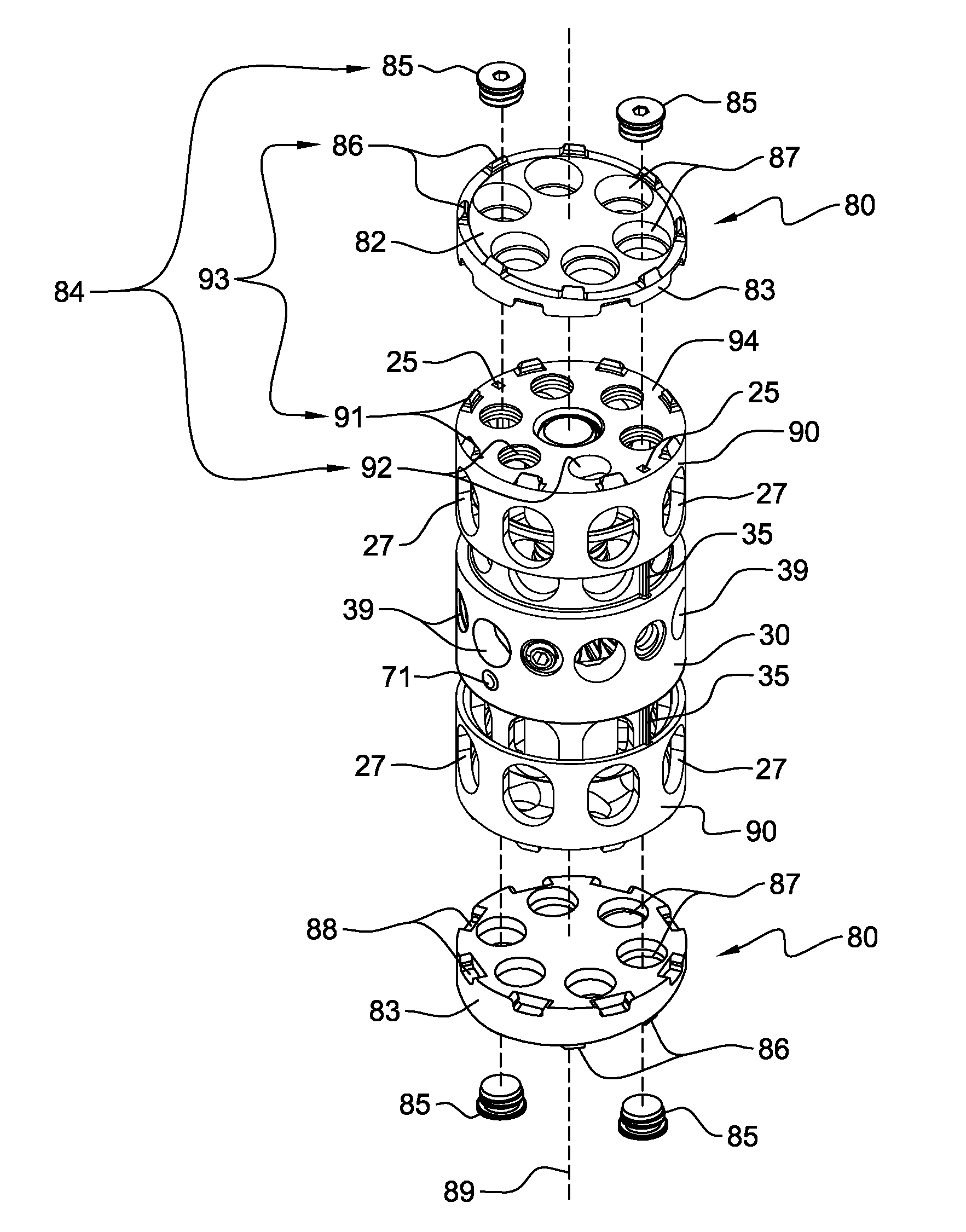
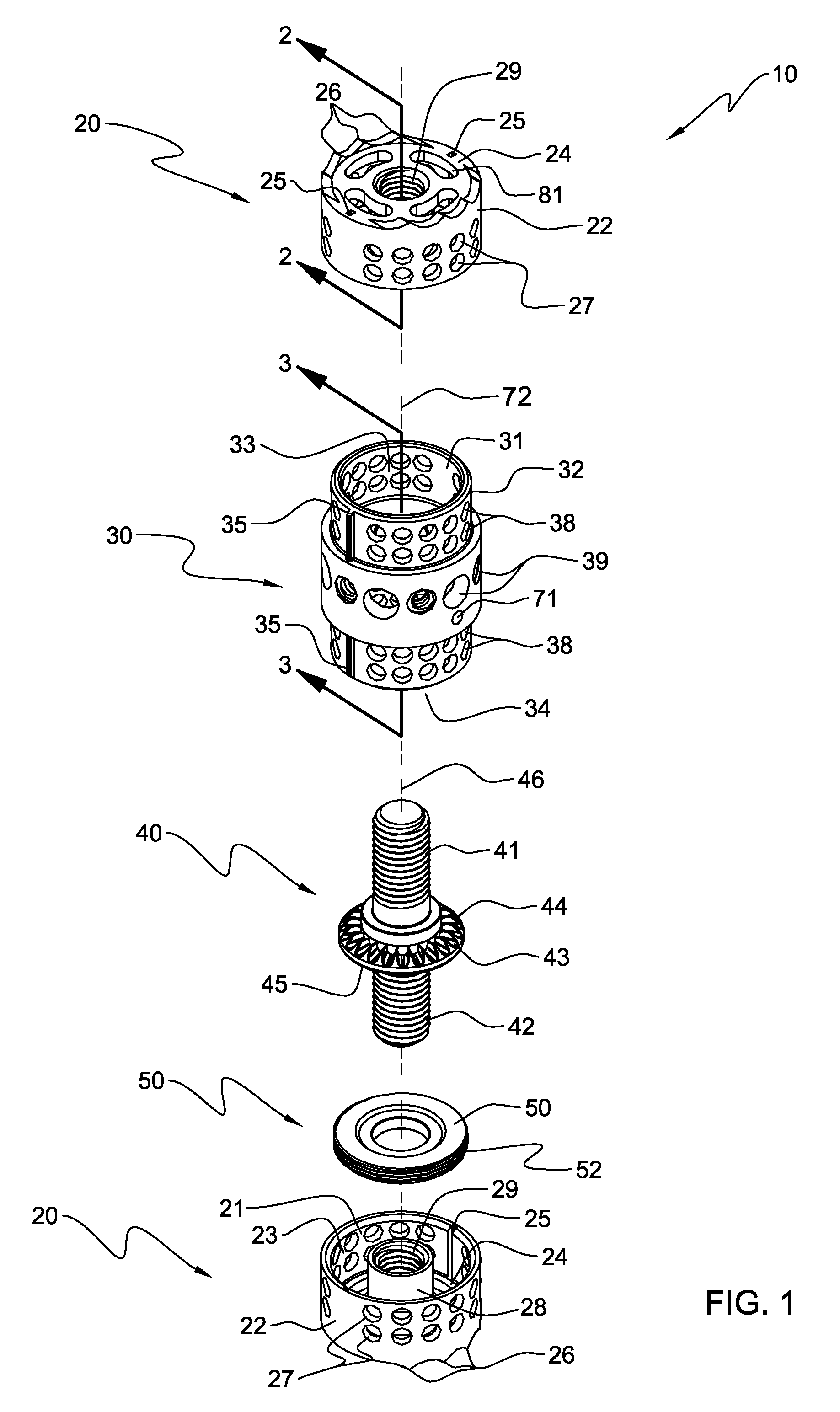
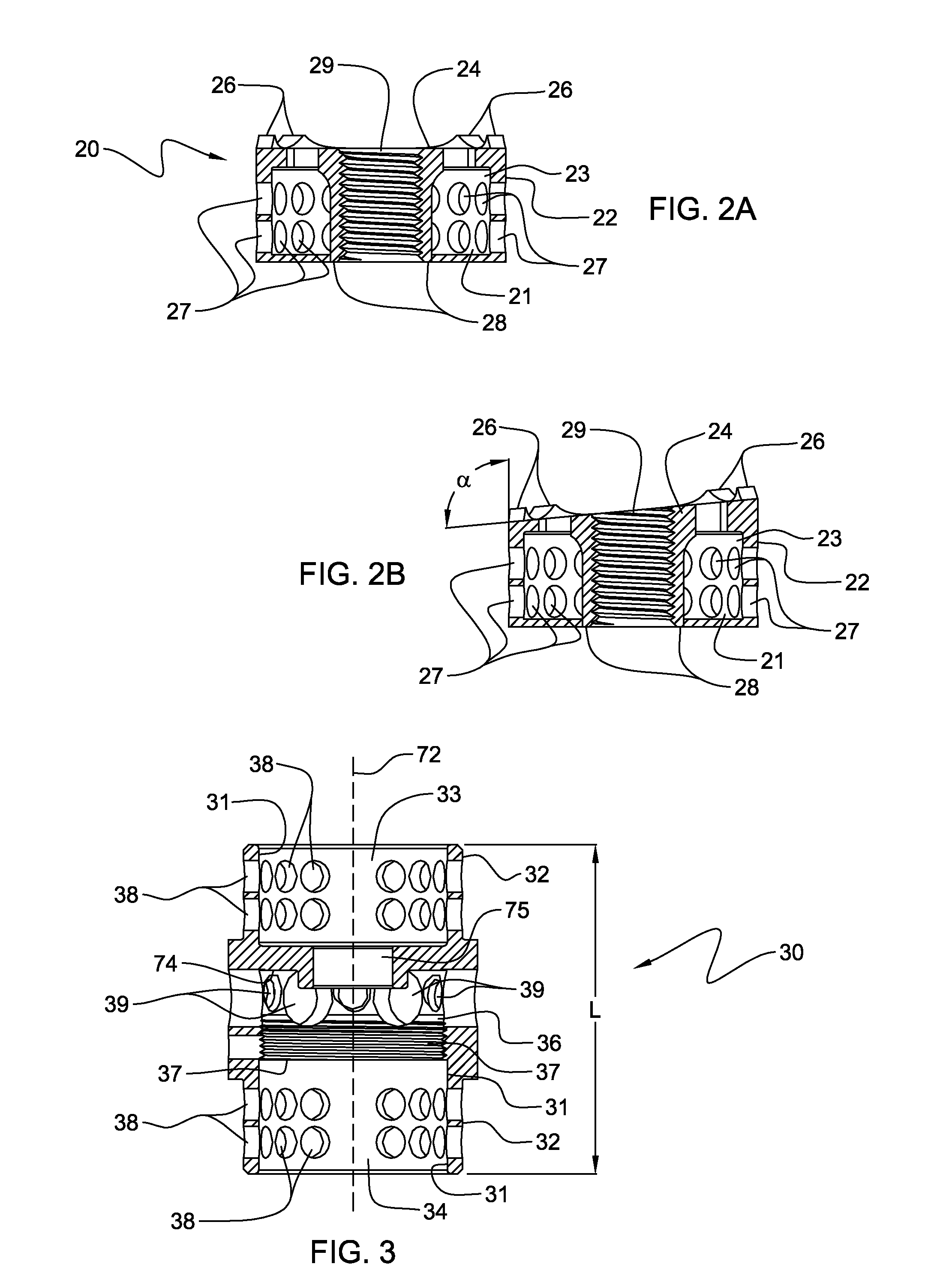
[0025]Generally stated, disclosed herein is a vertebral body replacement device or vertebral spacer that typically includes a body member, a central rod member, a support ring, two end members and at least one footplate member. As used herein, the terms “vertebral body replacement device” and “vertebral spacer” may be used interchangeable as they essentially describe the same type of implant device. Further, described herein is a surgical method for using the vertebral body replacement device to maintain a space between two vertebral bodies within a patient suffering from a diseased or damaged spinal column.

[0026]As depicted in FIG. 1, the general arrangement of a vertebral body replacement device 10, in accordance with an aspect of the present invention, includes a body member 30, at least two end members 20, a central rod member 40 and a support ring 50. In this detailed description and the following claims, the words proximal, distal, anterior, posterior, medial, lateral, superio...


PUM


Abstract

The vertebral body replacement device includes a body member and a central rod member that has two threaded portions and is configured to be operatively associated with the body member. The device also includes a first end member and a second end member with the end members being configured to threadingly engage the threaded portions of the central rod member. The body member and the two end members are further constructed to inhibit rotational movement of the two end members when the device is positioned within a space within a spine as the two end members will engage the adjacent respective vertebral bodies following rotational actuation of the central rod member causing the end members to move in an axial direction relative to the body member, thereby allowing the two end members to apply a force to the two vertebral bodies. A surgical method using the device is also disclosed.

Description

CROSS-REFERENCE TO RELATED APPLICATIONS / PATENTS[0001]This application is related to concurrently filed and commonly owned U.S. Non-Provisional patent application Ser. No. 11 / 928,553, entitled “FOOTPLATE MEMBER AND A METHOD FOR USE IN A VERTEBRAL BODY REPLACEMENT DEVICE ” by REFAI et al.TECHNICAL FIELD[0002]The present invention relates generally to orthopaedic and neurosurgical implants used for insertion within the spine, and more specifically, but not exclusively, concerns devices implanted within the spinal column to replace a resected, fractured or diseased vertebral body and to maintain or reestablish proper spacing between the remaining adjacent vertebral bodies.BACKGROUND OF THE INVENTION[0003]Damage or disease that affects the integral structure of a vertebral body within an individual's spinal column may lead to neurologic impairment with possible permanent damage to the spinal cord as well as improper neck and back alignment. Maintaining anatomic spacing within the spinal ...

Claims


Application Information

Patent Timeline
Patent Type & Authority Patents(United States)
IPC IPC(8): A61F2/44
CPCA61F2/44A61F2/4637A61F2/30734A61F2230/0069A61F2002/2835A61F2002/30235A61F2002/3024A61F2002/30364A61F2002/30367A61F2002/30405A61F2002/30433A61F2002/30492A61F2002/30525A61F2002/3054A61F2002/3055A61F2002/30601A61F2002/30616A61F2002/30772A61F2002/30818A61F2002/4638A61F2220/0025A61F2220/0033A61F2220/0041A61F2/30744
Inventor REFAI, DANIELFARRIS, JEFFREY A.
Owner AESCULAP IMPLANT SYST
Why Eureka
Try Eureka