Methods and apparatus for mechanical reserve power sources for gun-fired munitions, mortars, and gravity dropped weapons

a technology of mechanical reserve power source and gun-fired munitions, which is applied in the direction of generator/motor, electric fuze, ammunition fuze, etc., can solve problems such as vibration of power sour

Active Publication Date: 2012-05-22
OMNITEK PARTNERS LLC
View PDF11 Cites 23 Cited by
  • Summary
  • Abstract
  • Description
  • Claims
  • Application Information

AI Technical Summary

Benefits of technology

[0027]It is noted that the disclosed mechanical reserve power sources with integrated inertial sensors may also be used in devices that only experience high acceleration levels upon impacting certain object or medium. In such applications, the present power generators with integrated inertial sensors can be used to determine the direction of the impact and the level of impact forces that are experienced, which would also provide information as to the physical characteristics of the impacted medium (e.g., its softness, elasticity and density). The power source could then generate enough energy for onboard electronics to make appropriate decisions and initiate programmed actions.

Problems solved by technology

Upon the release of the stored potential energy, the potential energy can cause vibration of the power source “mass-spring” elements (or equivalent mass-spring elements when structural flexibility is used for potential energy storage purposes).

Method used


Image

  • Methods and apparatus for mechanical reserve power sources for gun-fired munitions, mortars, and gravity dropped weapons
  • Methods and apparatus for mechanical reserve power sources for gun-fired munitions, mortars, and gravity dropped weapons
  • Methods and apparatus for mechanical reserve power sources for gun-fired munitions, mortars, and gravity dropped weapons

Examples


embodiment 35

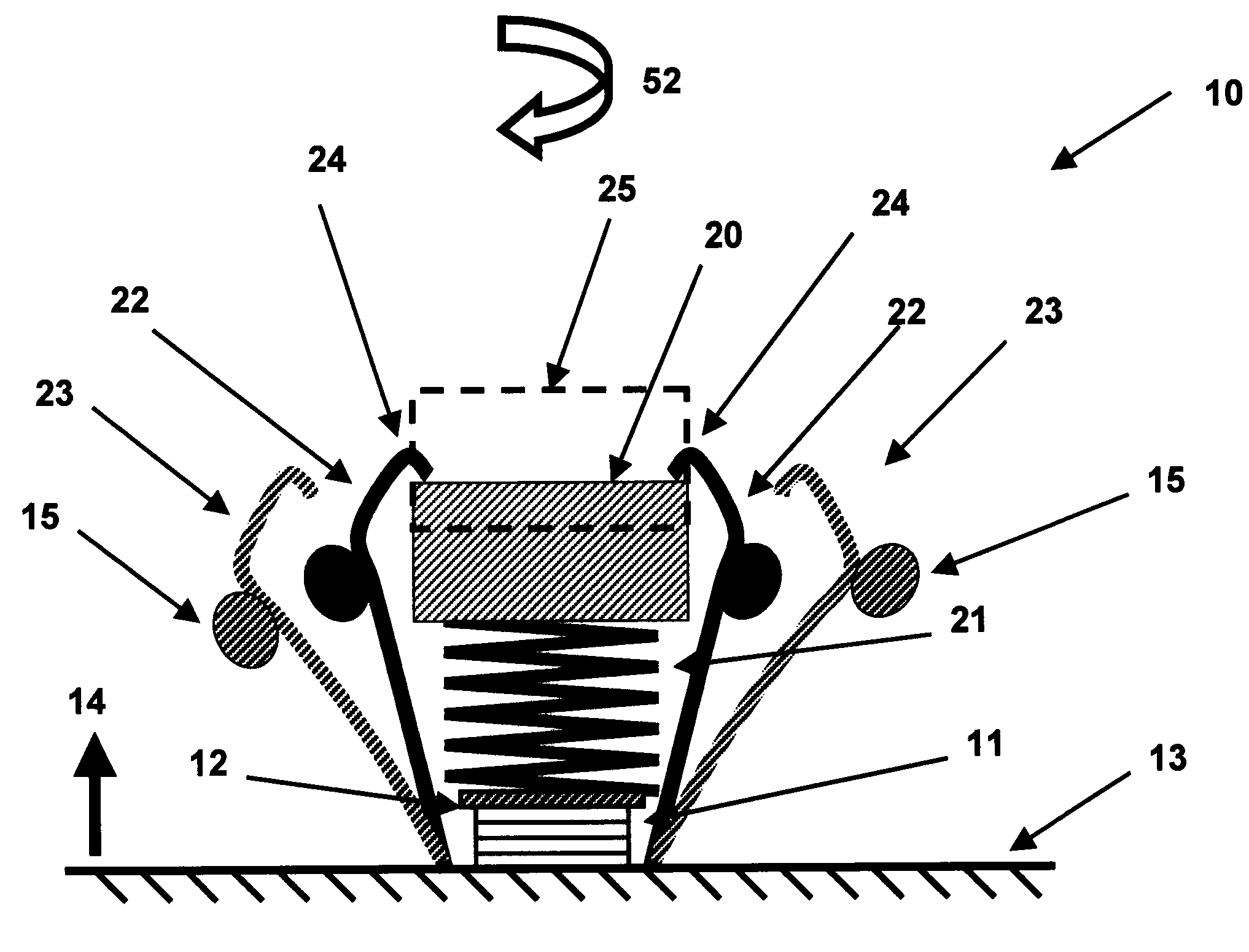
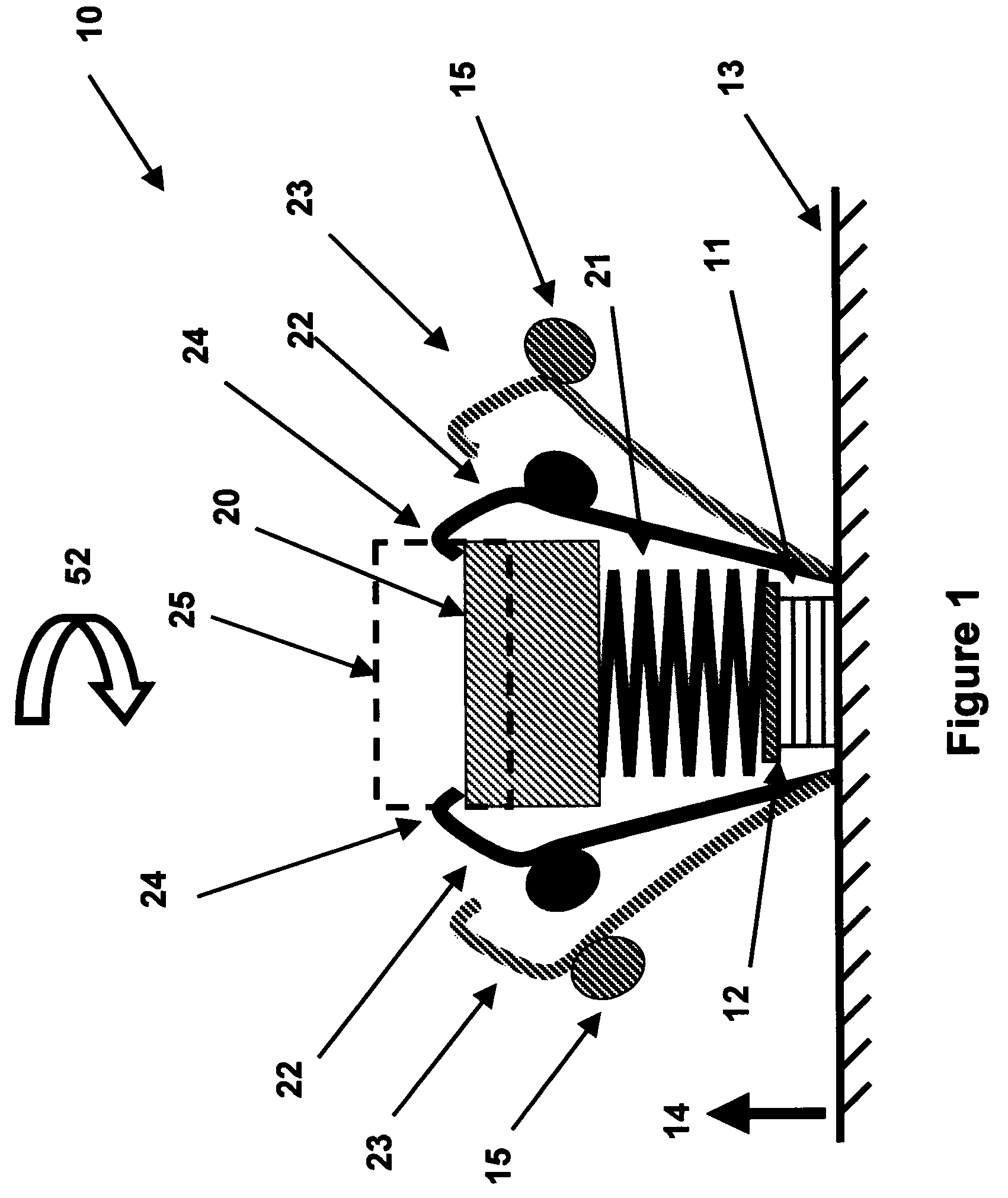
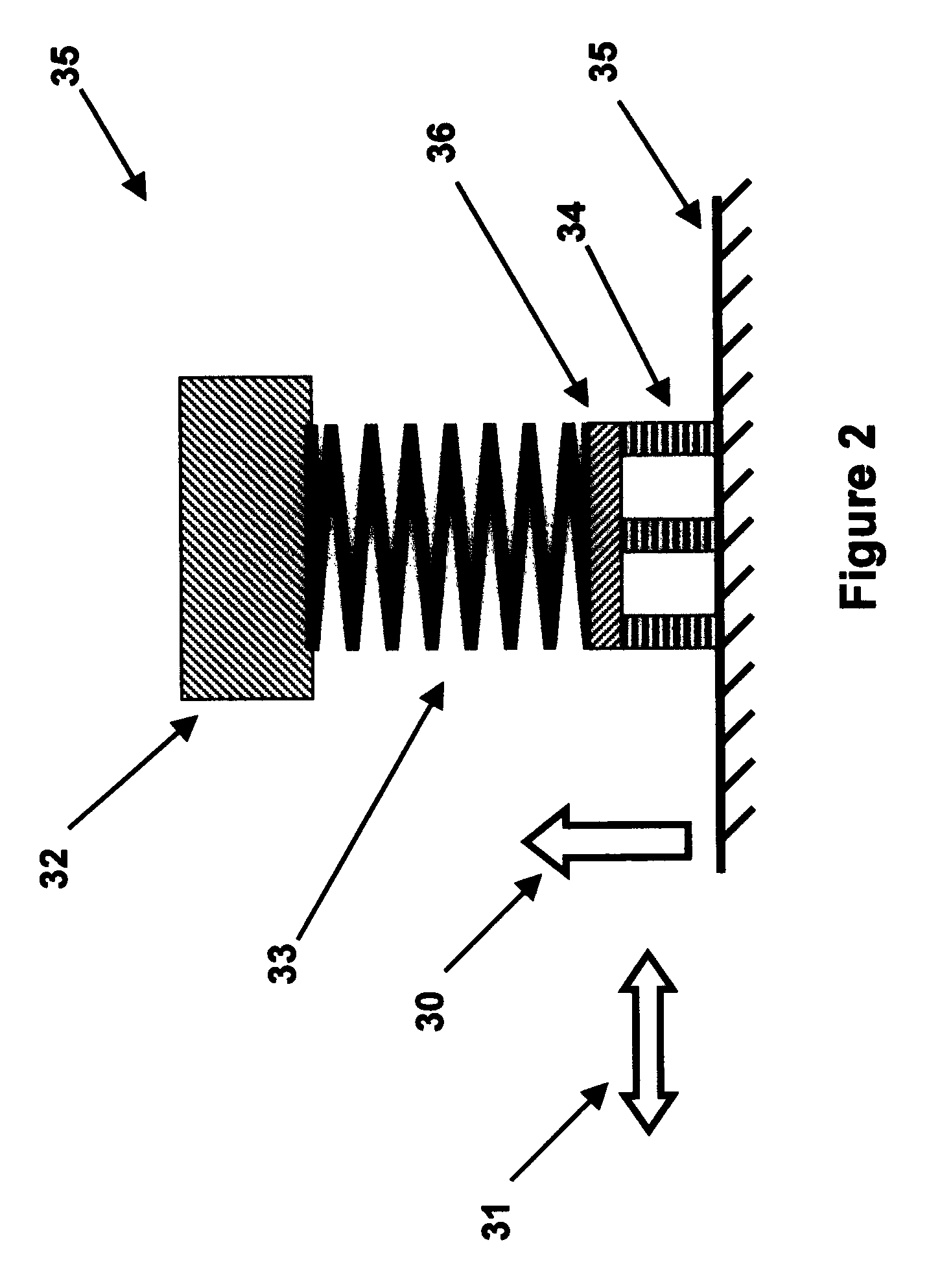
[0051]In the embodiment shown in FIG. 1, a single piezoelectric stack is used to convert mechanical energy to electrical energy. Alternatively, the piezoelectric element 11 can consist of more than one (preferably stack type) elements as shown in FIG. 2. In the schematic of FIG. 2, the locking elements 22 (FIG. 1) are not shown. In this alternative embodiment 35, the spring element 33 is also preferably attached to the piezoelectric elements 34 via a substantially rigid element 36 to distribute the forces applied by the spring element 33 more uniformly to the piezoelectric elements 34. The piezoelectric elements 14 are in turn attached (directly or via other substantially rigid elements (not shown) to the structure of the projectile 35.

[0052]During the firing, during the flight and during the impact at the terminal point of the flight, the projectile is subjected to axial and radial accelerations in the direction of the arrows 30 and 31, respectively, and rotary accelerations about ...

embodiment 40

[0057]In the embodiment shown in FIG. 1, the mechanical potential energy is stored in the spring element 21 of the mechanical reserve power source 10 by preloading the spring element in compression. Alternatively, the mechanical reserve power source may be designed such that the mechanical potential energy is stored in a spring element which is preloaded in tension. The schematic of such an embodiment 40 is shown in the schematic of FIG. 3. The mechanical reserve power source 40 is considered to be mounted to the structure 41 of a gun-fired projectile, in which it is intended to start to generate electrical energy upon firing. The firing acceleration is considered to be in the direction of the arrow 42. The mass element 43 is attached to the piezoelectric stack 44 via the spring 45, via an intermediate rigid element 46 to more uniformly distribute the force applied by the spring element 45 to the piezoelectric stack 44. The intermediate element 46 and the mass element 43 can be inte...

embodiment 10

[0062]In general, the locking mechanisms are preloaded in the direction opposing their release. For example in the embodiment 10 of FIG. 1, the locking elements 22 (acting as flexural spring element) are preferably preloaded such that normally they would press against the mass element 20. The purpose of this preloading and the threshold force for the release of the locking element 22 is to prevent accidental release of the locking mechanism such as in the case of accidental drops or other unintended acceleration or spinning of the projectile 13.

[0063]The amount of preload of the springs 21 and 45 of the mechanical reserve power sources of the embodiments of FIGS. 1 and 3 and the locking mechanism release threshold can be selected such that during accidental dropping of the power source and / or projectile (device) in which they are mounted, the springs 21 and 45 do not transmit any significant amount of force to the piezoelectric stack elements 11 and 44, respectively, thereby no sign...


PUM


Abstract

A power source including: a power generation device; a mass-spring unit having a mass and an elastic element operatively connected to the power generation device; and one or more retention fingers releasably engaged with the mass-spring unit for retaining the mass-spring unit in a position such that potential energy is stored therein and for releasing the potential energy upon occurrence of an event to generate electrical energy in the power generation device, the one or more retention fingers having a first end fixed at a base and a second end releasably engaged with the mass-spring unit. The occurrence of the event can be one or more of an acceleration and spinning of the base. Also disclosed is a power source having one or more retention fingers that are slidable with respect to a base such that the engagement of the first end is released upon a spinning of the base.

Description

BACKGROUND OF THE INVENTION[0001]1. Field of the Invention[0002]The present disclosure relates generally to reserve electrical power sources, and more particularly, to reserve power sources for munitions such as air dropped weapons and projectiles fired by guns, mortars and the like, that are initiated during the deployment of munitions to generate power from internally stored mechanical potential energy and when applicable, used to indicate certain events that can be used to achieve safe and arm functionalities or the like.[0003]2. Prior Art[0004]Chemical reserve batteries have long been used in various munitions, weapon systems and other similar applications in which electrical energy is required over relatively short periods of times. In addition, unique to the military is the need for munitions batteries that may be stored for up to twenty years without maintenance. Reserve batteries are batteries designed to be stored for years, even decades, without performance degradation. Re...

Claims


Application Information

Patent Timeline
Patent Type & Authority Patents(United States)
IPC IPC(8): H01L41/08
CPCF42C11/008F42C11/02F42C15/40
Inventor RASTEGAR, JAHANGIR S.
Owner OMNITEK PARTNERS LLC
Why Eureka
Try Eureka