Surveying instrument

a technology of a camera and a camera body, applied in the field of surveillance cameras, can solve the problems of extremely reduced working and achieve the effect of reducing the time to restore, quick re-detecting of the object reflector, and improving the efficiency of the measurement operation

Active Publication Date: 2012-05-22
KK TOPCON
View PDF31 Cites 5 Cited by
  • Summary
  • Abstract
  • Description
  • Claims
  • Application Information

AI Technical Summary

Benefits of technology

[0009]What the present invention obtains is to provide a surveying instrument with the tracking function, by which it is possible to quickly re-detect an object reflector, to reduce the time to restore the automatic tracking operation, and to improve an efficiency of the measuring operation, when the object reflector is missed and the automatic tracking operation cannot be performed.
[0011]The present invention provides a surveying instrument provided with the tracking function, the surveying instrument comprising a first image pickup means with a first solid image pickup element, a second image pickup means with a second solid image pickup element, an image pickup control instrument for controlling image pickup conditions of the first image pickup means and the second image pickup means, and a control unit for controlling the tracking operation of a target based on a target image signal obtained at the first solid image pickup element or based on a target image signal obtained at the second solid image pickup element, wherein the first image pickup means can acquire an image in wider range by the second image pickup means, and wherein the image pickup control instrument controls so that a target image is acquired by the first image pickup means when the target image is out of a photodetection range of the target of the second solid image pickup element and controls so that the target image is acquired by the second image pickup means when the target image detected by the first solid image pickup element is within the predetermined range. As a result, when a range where the tracking operation can be performed is increased and extended and when the target moves at high speed, an adequate action can be taken. Even when the target is missed out of sight and the automatic tracking operation cannot be carried out, the object reflector can be quickly re-detected. Accordingly, the time required to return to and to restore the automatic tracking operation is reduced, and an efficiency of the measuring operation is improved.
[0012]Also, the present invention provides the surveying instrument, wherein the control unit searches the target based on a target image signal obtained at the first solid image pickup element, and performs the collimation for a measurement based on a target image signal obtained at the second solid image pickup element. This makes it possible to perform quick searching in wider range by using a first image pickup means with wider range for the searching of the target. With respect to the tracking and the measurement, high accuracy can be assured by using a second image pickup means with wider range.
[0013]Further, the present invention provides the surveying instrument, wherein the predetermined range including an optical axis of the second image pickup means is set up, and when a photodetection position of the target by the second solid image pickup element is included in the predetermined range, the mask processing is performed on the second solid image pickup element so that a photodetection signal of the predetermined range is acquired, and the tracking operation is performed based on the photodetection signal of the predetermined range. This makes it possible to reduce an interference of a noise and to prevent an erroneous operation. Also, an amount of a data processing can be reduced and a burden of the data processing can be alleviated, and a processing speed can be increased.
[0014]Also, the present invention provides the surveying instrument, when a photodetection position of the target is out of the predetermined range, the mask processing is canceled and the tracking operation is performed based on a photodetection signal from the second solid image pickup element. As a result, it is possible to prevent the erroneous operation, to have a high efficiency of the data processing, and to reduce the range of tracking by the procedure of the mask processing.

Problems solved by technology

Further, under working conditions where the optical path is frequently intercepted by the obstacle, there are problems in that a working efficiency of the measurement operation is extremely decreased.

Method used


Image

  • Surveying instrument
  • Surveying instrument
  • Surveying instrument

Examples


Embodiment Construction

[0022]A description will be given below on a best aspect for carrying out the present invention by referring to the attached drawings.

[0023]First, referring to FIG. 1 to FIG. 3, a description will be given on general features of a surveying instrument, in which the present invention is carried out.

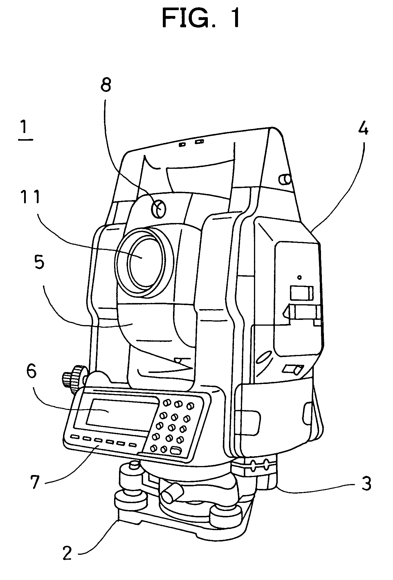
[0024]FIG. 1 shows a surveying instrument 1, in which the present invention is carried out. The surveying instrument 1 used in the invention is a total station, for instance. A pulsed laser beam is projected toward a measuring point. Then, a reflection light from the measuring point is received, and a distance is measured for each pulse. By averaging the results of a distance measurement, the distance measurement with high accuracy can be achieved.

[0025]The surveying instrument 1 primarily comprises a leveling unit 2 installed on a tripod which is not shown, a base unit 3 mounted on the leveling unit 2, a frame unit 4 rotatably mounted on the base unit 3 around the vertical axis, and a tel...


PUM


Abstract

The present invention provides a surveying instrument provided with a tracking function, said surveying instrument comprising a first image pickup means 40 with a first solid image pickup element 33, a second image pickup means 37 with a second solid image pickup element 19, an image pickup control instrument for controlling image pickup conditions of said first image pickup means and said second image pickup means, and a control unit for controlling the tracking operation of a target 36 based on a target image signal obtained at the first solid image pickup element or based on a target image signal obtained at the second solid image pickup element, wherein the first image pickup means can acquire an image in wider range by said second image pickup means, and wherein the image pickup control instrument controls so that a target image is acquired by the first image pickup means when the target image is out of a photodetection range of the target of the second solid image pickup element and controls so that the target image is acquired by the second image pickup means when the target image detected by the first solid image pickup element is within the predetermined range.

Description

BACKGROUND OF THE INVENTION[0001]The present invention relates to a surveying instrument, and in particular, to a surveying instrument with a tracking function.[0002]As a surveying instrument for measuring a distance, a horizontal angle and a vertical angle, a surveying instrument provided with a tracking function has been known in the past. In this type of the surveying instrument, an object reflector (target) such as a corner cube is collimated by a collimating telescope provided on the surveying instrument. A tracking light is projected from the collimating telescope, and when the target is moved, a reflection light from the target is received and the target can be automatically tracked.[0003]Normally, in a surveying instrument with the tracking function, no operator is assigned on a surveying instrument side. A target is supported by a surveying operator, and the target is moved by the surveying operator for each measuring point. In case a moving speed of the target exceeds a fo...

Claims


Application Information

Patent Timeline
Patent Type & Authority Patents(United States)
IPC IPC(8): G01C3/14
CPCG01C15/002G01S17/66
Inventor KUMAGAI, KAORUSAITO, MASAHIRO
Owner KK TOPCON
Why Eureka
Try Eureka