
Dynamic spur avoidance for high speed receivers

a high-speed receiver and dynamic technology, applied in the direction of transmission, electrical apparatus interference reduction, electrical apparatus, etc., can solve the problems of affecting measurement, spurious responses can be eliminated, etc., to achieve the effect of maximizing speed, reducing spurious responses, and reducing overall spur search tim

Active Publication Date: 2012-05-22
ANRITSU CO
View PDF5 Cites 20 Cited by
  • Summary
  • Abstract
  • Description
  • Claims
  • Application Information

AI Technical Summary

Benefits of technology

"The present invention provides methods and systems for overcoming problems with spur avoidance in high-speed receivers. The system dynamically changes the final intermediate frequency conversion based on the current radio frequency measurement to avoid spurious responses. An algorithmic component selects an optimum frequency plan that avoids spurious responses based on noise floor / bandwidth information and spur computations. The system includes a receiver with a variable local oscillator input, an IF output set with the LO to avoid spurs, and an input RF signal. A training signal can be applied to the IF filter input to determine any required gain calibration coefficients. The system noise floor is dependent on system settings, and the characteristics of the noise floor are used to form a look up table. The frequencies of the LO, sample clock, constituent oscillators, and the transit clock can be selectively controlled based on the spur avoidance algorithm. The system uses a look up table and computations to determine spurious responses and selects a frequency plan that avoids spurious responses. The system can also adjust IF filtering and digital filtering to eliminate spurs. The patent text provides technical means to improve spur avoidance in high-speed receivers."

Problems solved by technology

Spurious responses can affect the measurement if the spur amplitude exceeds nominal noise floor levels.

Method used


Image

  • Dynamic spur avoidance for high speed receivers
  • Dynamic spur avoidance for high speed receivers
  • Dynamic spur avoidance for high speed receivers

Examples


Embodiment Construction

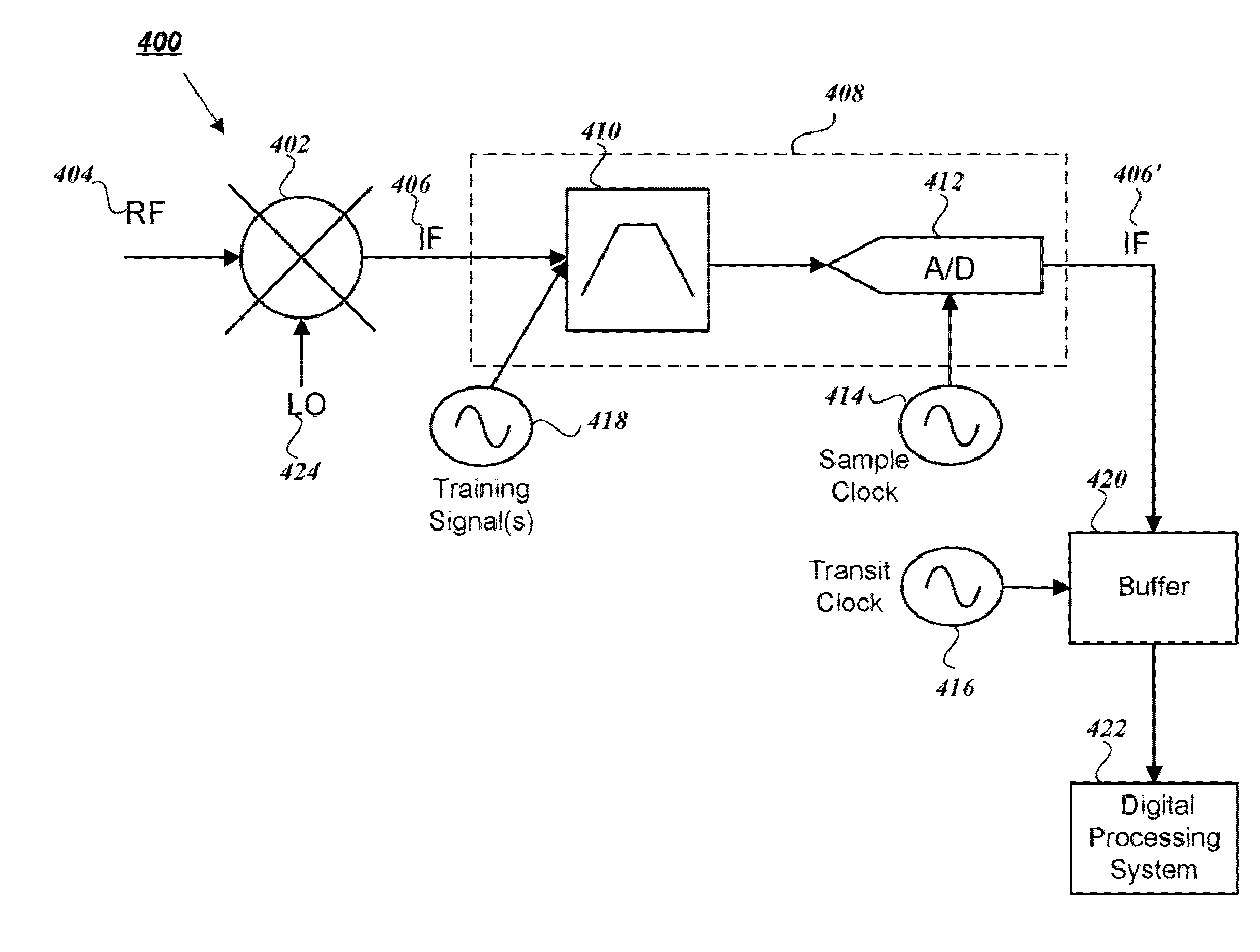
[0025]FIG. 4 illustrates components of a measuring receiver system 400 for avoiding spurious responses in a high speed receiver environment according to embodiments of the present invention. The measuring receiver system 400 includes a downconversion stage 402. The downconversion stage receives a radio frequency (RF) input signal 404 and converts the RF input signal 404 into an intermediate frequency (IF) signal 406. The term measuring receiver and measurement are used here, but the techniques apply as well to general receivers where a large dynamic range and fast frequency switching are required.

[0026]The IF signal 406 is accepted into an IF section 408. IF section 408 can include an IF filter 410 (here shown to be a bandpass filter) and an analog-to-digital (A / D) converter 412. An example of the IF filter can be an anti-aliasing filter. When using the anti-aliasing filter, the range of IF frequencies available for each RF frequency can be determined based on the pass band of the a...


PUM


Abstract

A system and method for implementing dynamic spur avoidance in a high speed receiver environment is provided. For a plurality of radio frequency (RF) input signal ranges, a range of intermediate frequency (IF) signals and a noise floor for each IF signal is determined. An identification of spurs that will affect the noise floor is also determined from a look up table for each range of the RF inputs. A frequency plan that sets local oscillator and constituent oscillator signals is selected such that the IF signals generated from the RF input will avoid lower order spurious responses of the identified spurs within the IF signal range.

Description

FIELD OF THE INVENTION[0001]The present invention relates to systems and methods for dynamic spur avoidance in high speed receivers.BACKGROUND OF THE INVENTION[0002]All high speed receivers generally experience some kind of spurious responses. These responses are often caused by undesired, but reasonably predictable, contamination signals riding on the radio frequency (RF) or local oscillator (LO) signals that convert unintentionally to the intermediate frequency (IF) signal, and hence get recognized as a desired response.[0003]These contamination signals can arise from many sources, e.g., reference clocks, digital signaling frequencies, component frequencies used in the creation of the RF or LO signal and strong external interferers. Sometimes it is possible to avoid these spurious responses by dynamically changing the configuration of the receiver, such as by changing the constituent makeup of the RF or LO signal. The problem of spurious responses becomes more apparent in the case...

Claims


Application Information

Patent Timeline
Patent Type & Authority Patents(United States)
IPC IPC(8): H04B1/10
CPCH04B15/06
Inventor MARTENS, JON S.LIN, OGGI P.ALBRECHT, THOMAS J.KAPETANIC, PETER A.
Owner ANRITSU CO
Learn More