Method and apparatus providing a graphical user interface for representing and navigating hierarchical networks

Inactive Publication Date: 2012-05-22
CISCO TECH INC
View PDF37 Cites 128 Cited by
  • Summary
  • Abstract
  • Description
  • Claims
  • Application Information

AI Technical Summary

Benefits of technology

[0026]By providing an interface of this sort, any type of hierarchical data can be repre

Problems solved by technology

Various problems are present in the ways in which prior art systems display and navigate through hierarchically arranged data.
The problem with this is that once the desired object (i.e., networked device or file or other data) is arrived at, the user can no longer see a general representation of the folders, files, network devices, network structure or hierarchical data at the same level or above the parent folder, other than the data immediately surrounding the object displayed.
This is because the tree-like display or an extended graphical representation of a network segment only provides a limited amount of space for displaying various levels of hierarchical data, and there is little scalability to different levels of detail.
In other words, once more than a few heavily populated folders or network segments are expanded via user selection, the user quickly b

Method used


Image

  • Method and apparatus providing a graphical user interface for representing and navigating hierarchical networks
  • Method and apparatus providing a graphical user interface for representing and navigating hierarchical networks
  • Method and apparatus providing a graphical user interface for representing and navigating hierarchical networks

Examples


Embodiment Construction

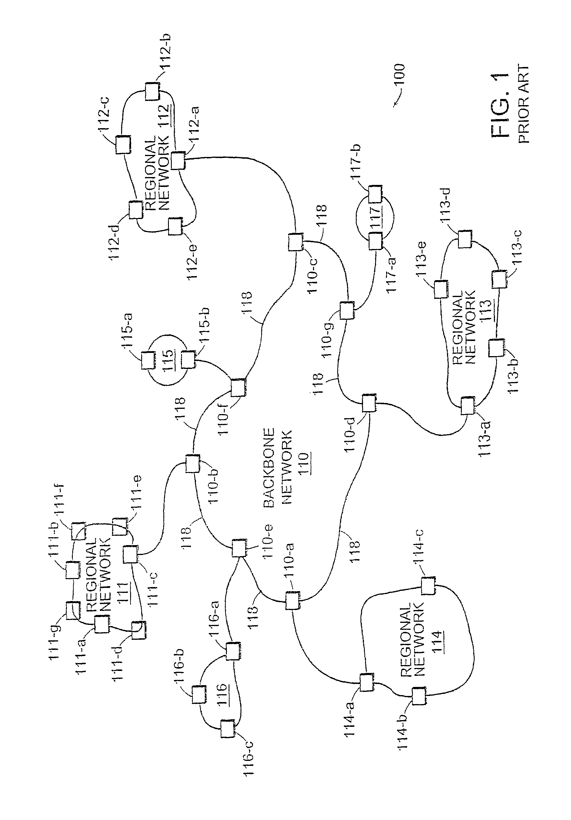
[0036]FIG. 1 illustrates a high level view of the architecture of a typical managed computer network 100. FIG. 1 is used to illustrate the concepts of hierarchical components and how a computer network can be viewed and represented as such. The invention, however, is not limited to being applied only to represent a hierarchical computer network architecture such as that of FIG. 1, even though preferred embodiments of the invention are well suited for this purpose. As will be explained in more detail later, the invention can be used to represent other forms of hierarchical data as well.

[0037]In FIG. 1, managed computer network 100 includes backbone network 110 which interconnects regional networks 111 through 117. Backbone network 110 is formed from high speed routers 110-a through 110-g interconnected with high speed data links 118. Each regional network 111 through 114 is formed from sets of routers labeled “a”, “b”, “c” and so forth within each regional network 111 through 117. Ma...


PUM


Abstract

A method and apparatus are provided which present hierarchical data to a user via a graphical user interface. In the interface, hierarchical data is represented by nodes, beginning with one or more top nodes and extending into lower hierarchical levels by the display of child nodes, child's child nodes, and so forth. The arrangement of nodes on the graphical user interface is such that scaling portrays the various hierarchical levels, and nodes do not spatially interfere with one another. Navigation through the hierarchical data is provided by allowing the user to select any visible node, at which point a zoom-in or zoom-out view to the selected node as a centrally located node on the interface is performed.

Description

RELATED APPLICATIONS[0001]This application is a continuation of U.S. application Ser. No. 10 / 629,811, filed Jul. 29, 2003 now abandoned, which is a continuation of U.S. application Ser. No. 09 / 208,554, filed Dec. 9, 1998, now U.S. Pat. No. 6,628,304. The entire teachings of the above applications are incorporated herein by reference.COMPUTER PROGRAM LISTING APPENDIX[0002]A computer program listing in Appendix A on associated CD-ROM and duplicate CD-ROM having file name “2386-1034-001 Appendix A—Source Code.txt”, created Jul. 18, 2003, 46.2 Kbytes is being filed concurrently herewith; the entire teachings inherent therein are incorporated herein by reference.FIELD OF THE INVENTION[0003]The present invention relates to graphical user interfaces, and more specifically, to a computer system employing a software application providing a specialized graphical user interface to efficiently manage, view and navigate relationships between objects having hierarchical relationships with one ano...

Claims


Application Information

Patent Timeline
IPC IPC(8): G06F15/177G06F3/033G06F3/048H04L12/24
CPCG06F3/0481H04L41/044H04L41/20H04L41/22
Inventor MITCHELL, FREDERICK H.BAINBRIDGE, DAVID K.
Owner CISCO TECH INC
Why Eureka
Try Eureka