Adjustable fishing outrigger apparatus

a technology of fishing outrigger and adjustment rod, which is applied in fishing, special-purpose vessels, machine supports, etc., can solve the problems of difficulty and hazards of outrigger pole in a deployed position, limited benefits of doing so, and short trolling rod length

Active Publication Date: 2012-05-29
EASTERN METAL SUPPLY
View PDF97 Cites 14 Cited by
  • Summary
  • Abstract
  • Description
  • Claims
  • Application Information

AI Technical Summary

Benefits of technology

[0013]The invention relates to an adjustable fishing outrigger apparatus for selectively positioning the outrigger pole outboard of a fishing vessel to deploy the pole from a stowed position to a deployed position and / or to re-position the pole between different deployed positions for fishing and / or for rigging the outrigger pole in to a stowed position when not fishing. Although subject to some variation based on the configuration of a particular vessel and the preferences of its captain, the stowed position is typically at least somewhat elevationally-lowered relative to a deployed position, so that the outrigger pole can clear bridges or other overhead obstacles beneath which the vessel pass, and is rotated in at least somewhat inboard so the vessel can pass by other vessels, dockside structures or the like without danger of the outrigger pole striking them.
[0021]In a preferred form, the latch is one which includes first and second mutually engageable latch members of mutually complementary shape, one of which is rotationally fixed, the other of which is coupled to a rotating element of the ball screw assembly for rotation therewith. The latch includes a slip coupling which is driveably interposed between the ball screw assembly and which is biased to cause the mutually engageable latch members to engage one another, thereby resisting rotation of the rotating element of the ball screw assembly, and thus also resisting change in the position of the outrigger pole, unless a biasing force is deliberately overcome by a force in a direction effective to actuate the slip coupling in a direction which disengages the mateable latch members. The slip coupling allows the latch to be forcibly biased in favor of engagement of the mutually engageable latch members. Preferably, the slip coupling is oriented such that at least a portion of the overall magnitude of the biasing force is generated by gravity due the weight normally acting on the slip coupling when the outrigger apparatus is not being deliberately rotatably driven, thus causing the apparatus to resist undesired or unexpected changes in the position of the outrigger pole without need of a user taking any deliberate action to engage the latch.

Problems solved by technology

However, since the width, or “beam” of any given vessel is limited, so too is the number of fishing lines which can be trailed from the vessel without undue risk of becoming entangled.
Although a fishing rod can be positioned so that the tip of the rod reaches out over the water to the port or starboard of the vessel, the benefit of doing so is limited by the length of the fishing rod.
Since they are subjected to significant forces due to the hydraulic drag associated with trolling a bait, not to mention the forces generated when attempting to bring in a large and powerful fish, trolling rods tend to stout but relatively short, especially the type of rods used for trolling for saltwater game fish.
Particularly when a vessel is near a dock, in a harbor or anywhere other than relatively open water, an outrigger pole in a deployed position can present difficulties and hazards, even if a vessel is stationary but particularly while a vessel is underway.
The elevation of the pole reduces the overall clearance to overhead obstacles, such as bridges.
When navigating in narrow channels or near dockside, or in the vicinity of other vessels, sufficient clearance may not be available.
Despite being relatively light in weight, the mass of an outrigger pole is not insignificant and loss of control over the outrigger pole could give rise to substantial safety hazards.
Particularly when a vessel is underway or even static under rough weather condition, an outrigger pole may experience a number of significant external forces.
The fishing line and bait also exerts a force on the outrigger pole due to hydraulic drag resulting from the vessel trolling them through the water.

Method used


Image

  • Adjustable fishing outrigger apparatus
  • Adjustable fishing outrigger apparatus
  • Adjustable fishing outrigger apparatus

Examples


Embodiment Construction

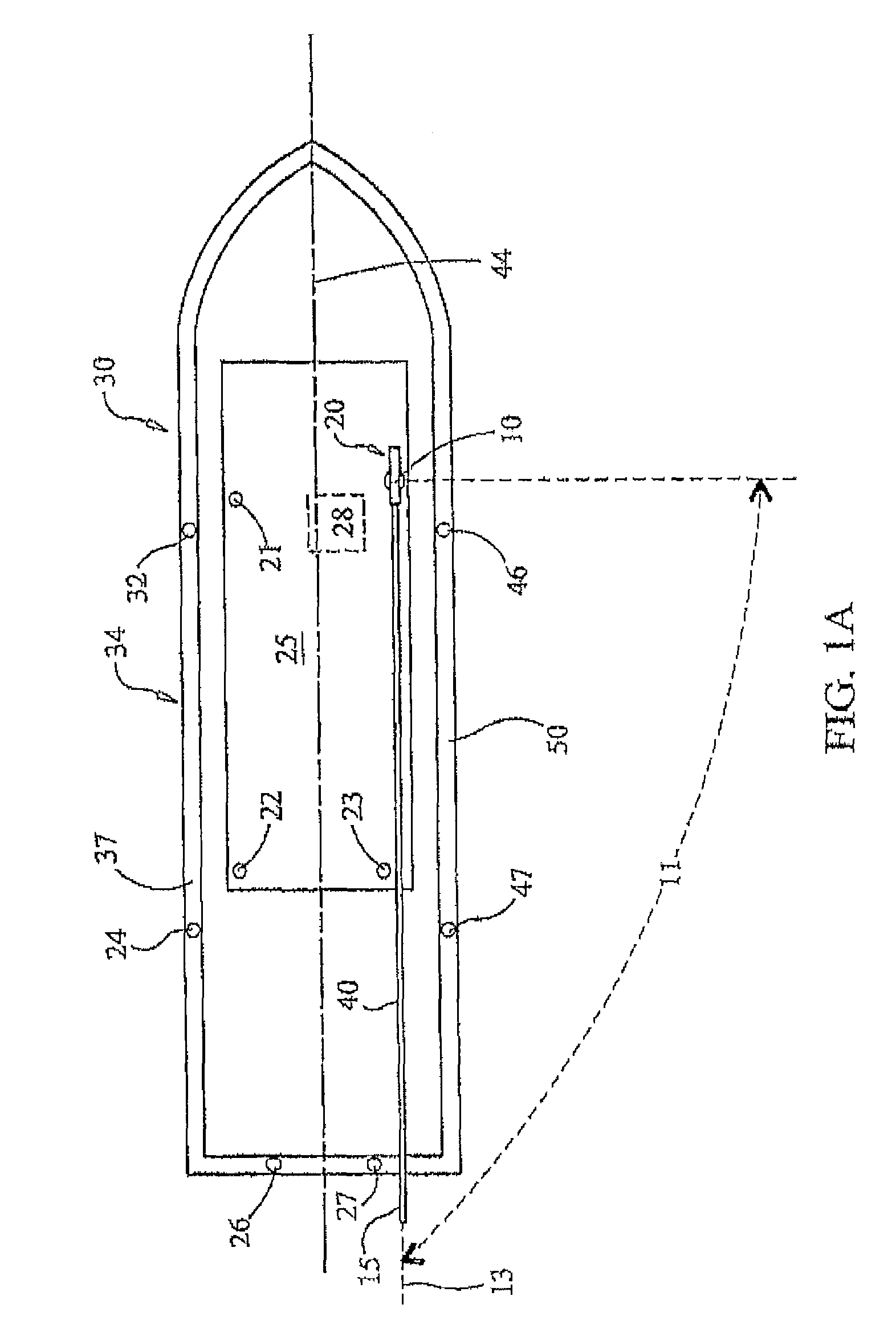
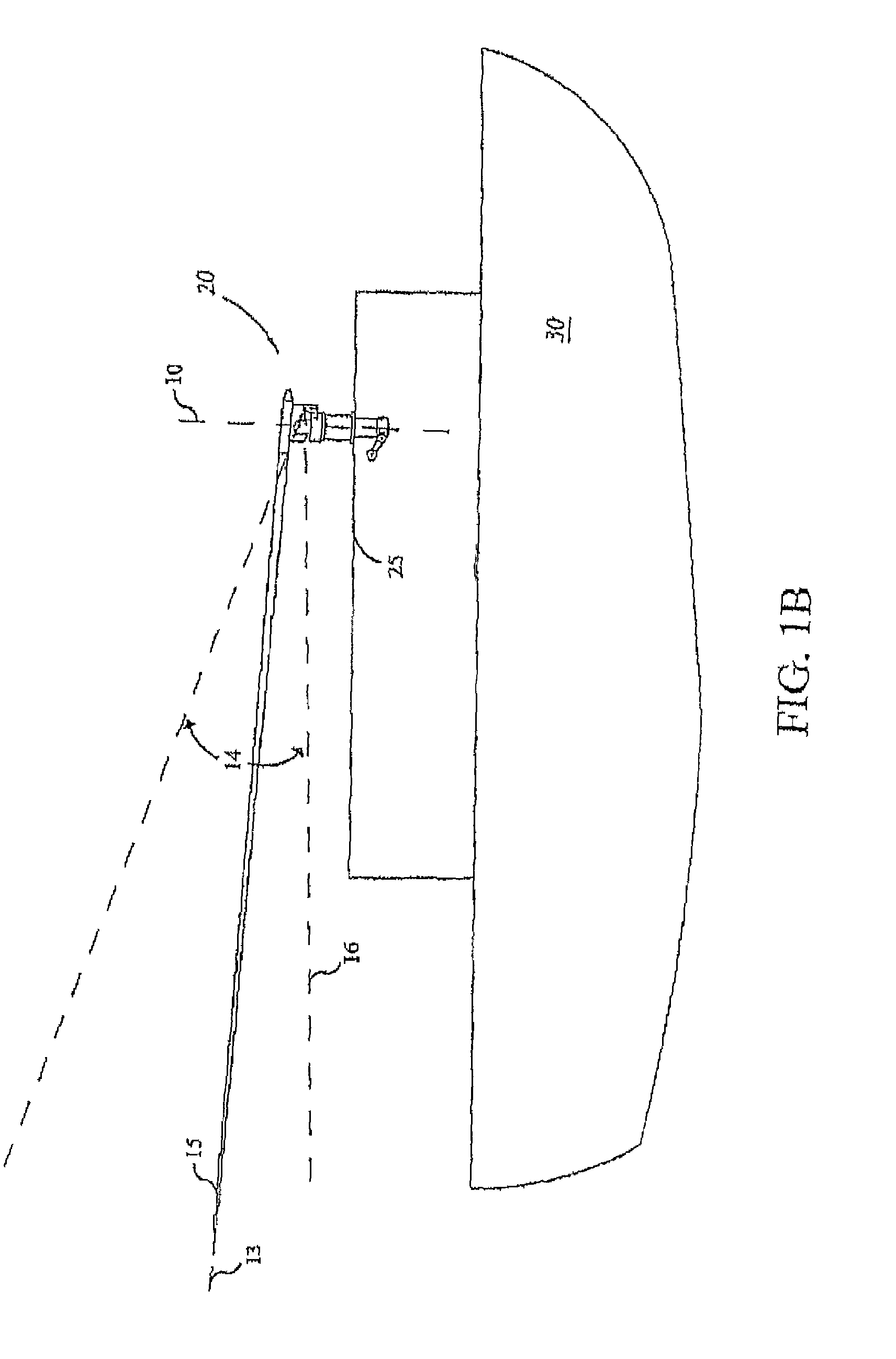
[0039]FIG. 1A is a schematic representation of a marine vessel 30 to which is mounted a first preferred embodiment of an adjustable outrigger apparatus 20. By way of non-limiting example, apparatus 20 is shown mounted to an overhead structure 25 beneath which is located the helm station 28 of the marine vessel 30. Overhead structure 25 could suitably be for example the roof of an enclosed or partially enclosed cabin or the roof of a marine t-top or an element of a marine tower, or half-tower structure. It is to be understood however that apparatus 20 could suitably be mounted elsewhere on vessel 30 such as closer to its port side 34 including without limitation locations such as location 21 or location 22 on overhead structure 25; location 24 or location 32, on the port side rail 37, or at location 26 atop the transom 36 of vessel 30. Alternatively, or in addition to, one or more of the foregoing locations, apparatus 20 could also suitably be mounted at various locations to the star...


PUM


Abstract

An adjustable outrigger for use on a marine vessel for supporting and selectively positioning a fishing outrigger pole includes a rotatable driving device which is coupled to a ball screw mechanism a rotatable member of which is coupled to a piston and to a track pitched in a direction along an axis to concurrently rotate the outrigger pole about the axis and angulate the outrigger pole in a plane perpendicular to that axis.

Description

CROSS-REFERENCE TO RELATED APPLICATIONS[0001]This application is a continuation-in-part of, and claims priority under 35 U.S.C. §120 to, co-pending U.S. patent application Ser. No. 11 / 600,320 filed Nov. 16, 2006 which in turn claims the benefit of U.S. Provisional Application Ser. No. 60 / 736,857 filed Nov. 16, 2005 under 35 U.S.C. §119(e) for all commonly disclosed subject matter. U.S. Provisional Application Ser. No. 60 / 736,857 and U.S. application Ser. No. 11 / 600,320 are each expressly incorporated herein by reference in their entirety to form a part of the present disclosure.FIELD OF THE INVENTION[0002]The invention relates to the field of fishing. More particularly, the invention relates to an adjustable fishing outrigger apparatus which supports and positions an outrigger pole of the type used for extending trolling lines outboard of a marine vessel. The apparatus includes a rotatably driven mechanism which positions the outrigger pole as desired at substantially any selected p...

Claims


Application Information

Patent Timeline
Patent Type & Authority Patents(United States)
IPC IPC(8): A01K97/10
CPCA01K91/08
Inventor WILCOX, SCOTT A.BAEZ, LAUDELINO
Owner EASTERN METAL SUPPLY
Why Eureka
Try Eureka