Apparatus for engine control

a technology for engine control and apparatus, applied in the direction of electric control, ignition automatic control, machines/engines, etc., can solve the problems of excessive ignition timing and engine stoppage, and achieve the effect of lowering the effective compression ratio

Inactive Publication Date: 2012-05-29
NISSAN MOTOR CO LTD
View PDF6 Cites 8 Cited by
  • Summary
  • Abstract
  • Description
  • Claims
  • Application Information

AI Technical Summary

Benefits of technology

[0007]It has been discovered that in a valve timing changing mechanism like that presented in Japanese Laid-Open Patent Publication No. H08-338295, when the intake valve timing (IVC) is later than a bottom dead center and an initial position of an open timing and an initial position of a close timing of the intake valve are retarded positions (e.g., when an initial position of an intake valve close timing is a most retarded position), an actuator is driven such that the open and close timings of the intake valve are changed from the initial positions to more advanced positions. If a drive device serving to drive the actuator in order to move the open and close timings of the intake valve to more advanced positions fails, then the open and close timings of the intake valve will return to more retarded positions such that an intake air quantity will decline and add to the knock suppressing effect of the Miller cycle, which acts to lower the effective compression ratio. As a result, the engine state will change to a safer region.

Problems solved by technology

As a result, the required ignition timing will become excessively advanced with respect to the set ignition timing and there will be the possibility that knocking will occur and the engine will stop.

Method used


Image

  • Apparatus for engine control
  • Apparatus for engine control
  • Apparatus for engine control

Examples


Embodiment Construction

[0021]Selected embodiments of the present invention will now be explained with reference to the drawings. It will be apparent to those skilled in the art from this disclosure that the following descriptions of the embodiments of the present invention are provided for illustration only and not for the purpose of limiting the invention as defined by the appended claims and their equivalents.

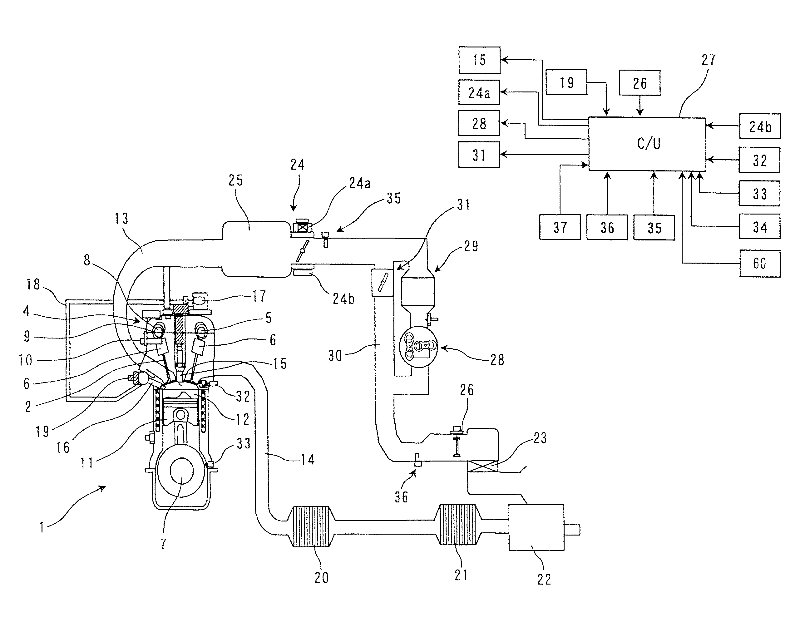
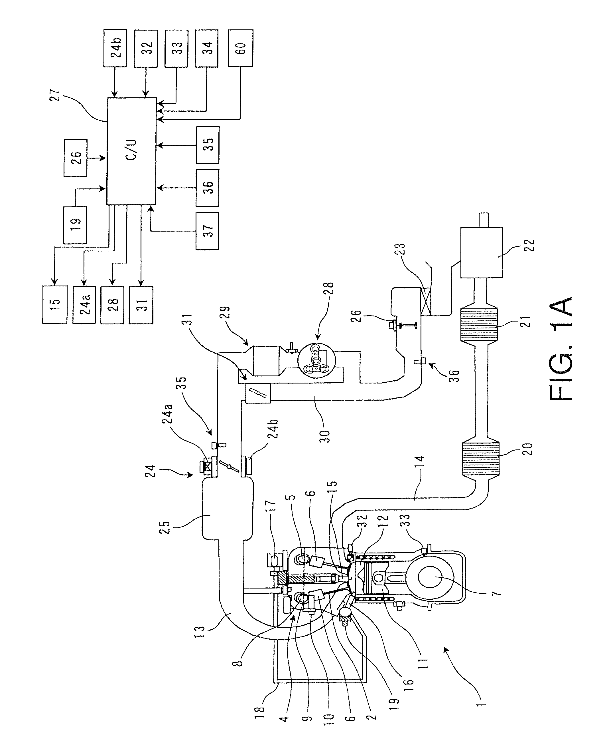
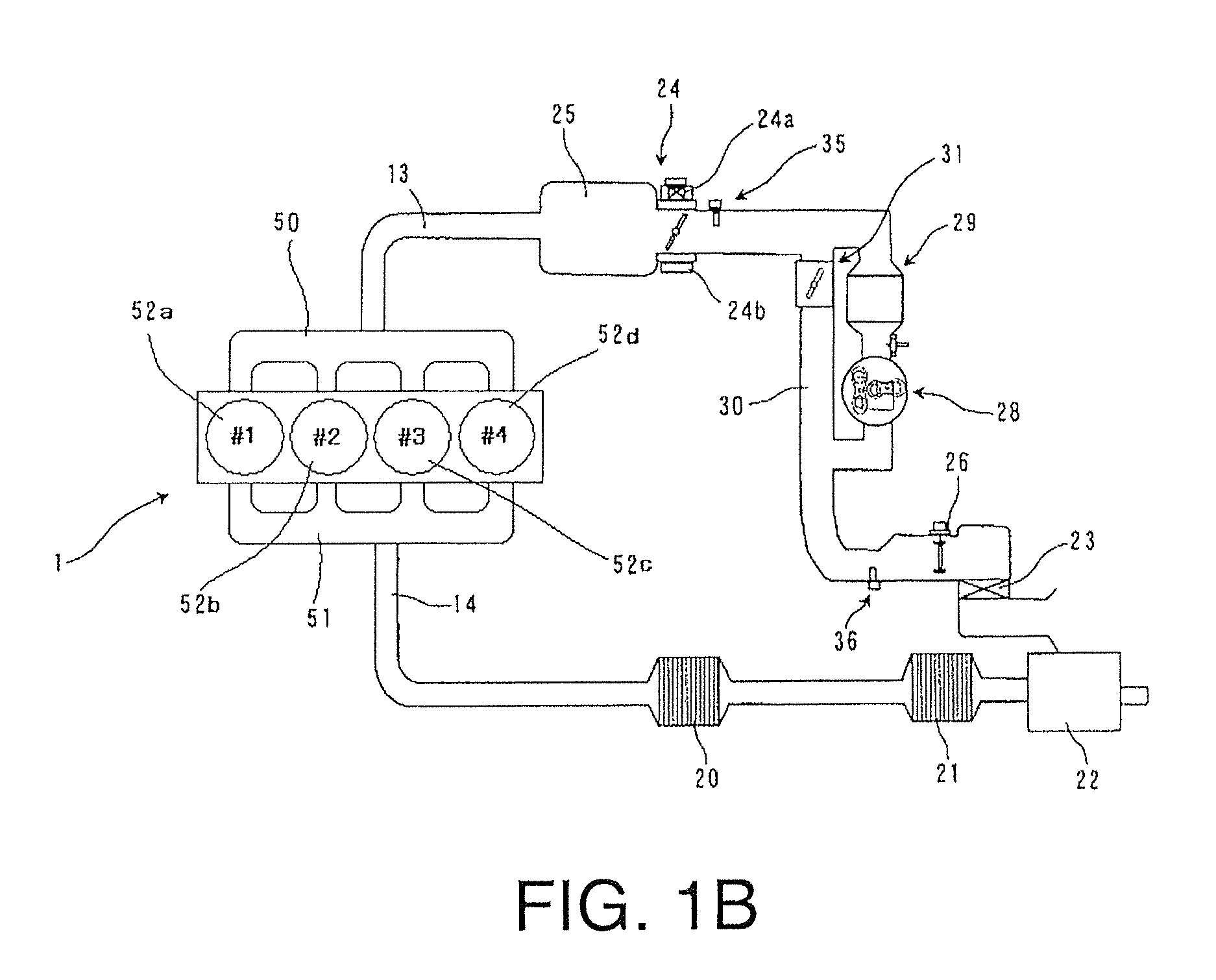
[0022]Referring initially to FIG. 1A and FIG. 1B, an internal combustion engine 1 is illustrated with an engine control apparatus in accordance with a first embodiment. The internal combustion engine 1 is a spark ignition gasoline engine in which a close timing of an intake valve 2 occurs after a bottom dead center. In other words, the internal combustion engine 1 operates according to a late intake valve closing Miller cycle. In this embodiment, for example, the internal combustion engine 1 is a 4-cylinder straight type engine. The 4-cylinder straight type engine has cylinders 52a (#1), 52b (#2), ...


PUM


Abstract

An engine control apparatus is provided with an engine, an ignition device, a valve timing changing mechanism, an intake valve close timing detecting device, a supercharger and a controller. The engine achieves a Miller cycle by the valve timing changing mechanism setting an intake valve close timing to occur after a bottom dead center timing. The controller controls an ignition timing of the ignition device, the open timing of the intake valve and the close timing of the intake valve. The controller retards the ignition timing during supercharging and when a detected value of the intake valve close timing is earlier than a target value of the intake valve close timing by at least a prescribed value in comparison with a situation in which the detected value matches the target value of the intake valve close timing.

Description

CROSS-REFERENCE TO RELATED APPLICATIONS[0001]This U.S. National stage application claims priority to Japanese Patent Application Nos. 2008-146537, filed on Jun. 4, 2008 and 2009-080782, filed on Mar. 30, 2009. The entire disclosures of Japanese Patent Application Nos. 2008-146537 and 2009-080782 are hereby incorporated herein by reference.BACKGROUND[0002]1. Field of the Invention[0003]The present invention generally relates to an internal combustion engine that operates according to a late intake valve closing Miller cycle in which an intake valve close timing is set to occur after a bottom dead center.[0004]2. Background Information[0005]A valve timing changing mechanism capable of advancing or retarding an open close timing of an intake valve is widely known. One example of such technology is disclosed in Japanese Laid-Open Patent Publication No. H08-338295.[0006]In view of the above, it will be apparent to those skilled in the art from this disclosure that there exists a need for...

Claims


Application Information

Patent Timeline
Patent Type & Authority Patents(United States)
IPC IPC(8): F02P5/06
CPCF01L1/143F01L1/3442F02D13/0238F02D13/0269F02D23/02F02D41/0002F02D41/221F02P5/1502F01L2001/34426F02B23/104F02B29/0418F02B2075/125F02D2041/001Y02T10/46Y02T10/144Y02T10/142Y02T10/42F02D41/0007F02P5/1521Y02T10/12Y02T10/40
Inventor KOBAYASHI, ATSUSHI
Owner NISSAN MOTOR CO LTD
Why Eureka
Try Eureka