Image processing apparatus

a technology of image processing and input image, which is applied in the field of image processing apparatus, can solve the problems of difficult to achieve the accurate setting of a desired area such as a polygon 73/b> at a remote location through the operation based on the mouse, difficult to achieve the accurate designation of the distance between the building and the area on the screen in accordance with the distance from the camera, and difficult to accurately create an interpolation formula on the basis of only an input image, etc., to facilitate visual

Active Publication Date: 2012-05-29
KOKUSA ELECTRIC CO LTD
View PDF24 Cites 8 Cited by
  • Summary
  • Abstract
  • Description
  • Claims
  • Application Information

AI Technical Summary

Benefits of technology

[0019]In the former method, information on size at an arbitrary position on an image can in principle be interpolated if an accurate interpolation formula can be obtained but the manual, accurate creation of such an interpolation formula on the basis of only an input image is very difficult. In other words, the number of positions of objects to be designated on the image is increased for the purpose of reducing errors but a sufficient number of objects whose true sizes are known are not always transcribed in the image. Ideally, visiting a spot concerned to acquire information about the camera installation status is unneeded and setting can preferably be carried out from a remote location while watching an input image.
[0021]The present invention is made in the light of the aforementioned conventional drawbacks and has for its object to provide an image processing apparatus which can visually facilitate setting by a user in performing setting of parameters necessary for image processing.
[0025]Accordingly, since an image is displayed on the second coordinate system on which, for example, the ground surface is transcribed as being kept to remain unchanged substantially in size irrespective of the distance and setting information is received from the user watching the image, visual setting by the user can be facilitated in, for example, setting of an area.
[0034]The reception means for receiving the information inputted by the user may be constructed by using an operation unit, for example, a mouse or keyboard operated by the user. The mode of receiving the information inputted by the user may include, for example, the mode of causing the user to operate the operation unit while watching an image on the second coordinate system displayed on the screen so as to input the information or the mode of displaying the information received from the user, such as the area size, length or numerical value, on the screen, thereby making it possible to promote the easy-to-handle capability for the convenience of the user.
[0036]According to the image processing apparatus, an image is displayed on a coordinate system on a plane representing reference and the setting information is received from the user watching the displayed image, thereby ensuring that setting by the user can be facilitated visually.

Problems solved by technology

Accordingly, in an image of display unit which displays an input image as it is, a location remote from the camera is displayed in a smaller size, giving rise to a problem that accurate setting of a desired area such as a polygon 73 at a remote location through the operation based on the mouse is difficult to achieve.
For example, when it is desired that an object approaching the interior of an area distant from a specified building by some meters be detected, accurate designation of the distance between the building and the area on the screen is difficult to achieve in accordance with the distance from the camera.
In the former method, information on size at an arbitrary position on an image can in principle be interpolated if an accurate interpolation formula can be obtained but the manual, accurate creation of such an interpolation formula on the basis of only an input image is very difficult.
The latter method for area division is also disadvantageous in that a highly graded skill is required to acquire proper divisions free from irregular errors with the knowledge of true sizes in respective areas.

Method used


Image

  • Image processing apparatus
  • Image processing apparatus
  • Image processing apparatus

Examples


embodiment 1

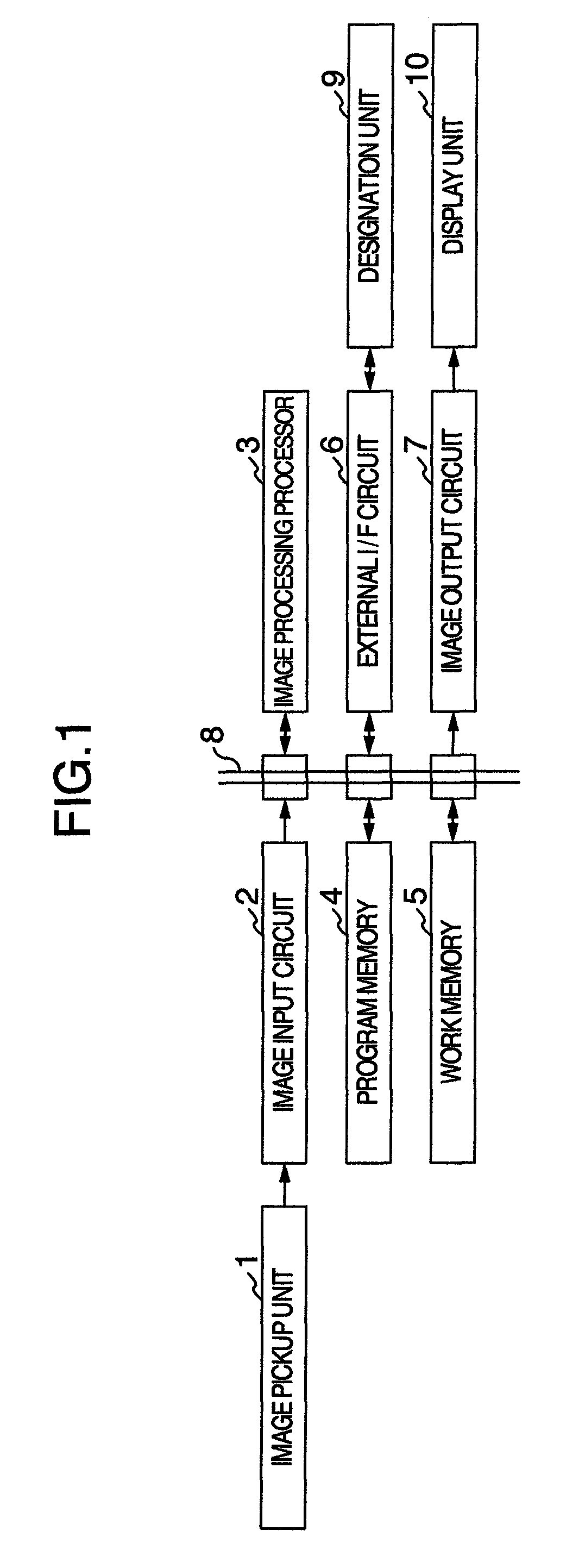
[0053]A monitor apparatus according to embodiment 1 of the present invention is constructed as exemplified in FIG. 1.

[0054]The exemplified monitor apparatus comprises an image pickup unit 1 constructed by using a camera, for example, an image input circuit 2, an image processing processor 3, a program memory 4, a work memory 5, an external I / F (interface) circuit 6, an image output circuit 7, a data bus 8, a designation unit 9 comprised of, for example, a mouse or a keyboard operated manually, and a display unit 10.

[0055]The image input circuit 2, image processing processor 3, program memory 4, work memory 5, external I / F circuit 6 and image output circuit 7 are coupled to the data bus 8.

[0056]The image pickup unit 1 used herein may include, for example, a unit for controlling the image pickup unit 1 and a unit for recording various external data.

[0057]An example of general operation performed in the monitor apparatus in embodiment 1 will be described.

[0058]The image pickup unit 1 i...

embodiment 2

[0112]In embodiment 2, the area parameter in the monitor apparatus of the previous embodiment 1 is adaptively set on the basis of a detection object representing a reference to enable an object approaching the reference object, for example, to be detected. Unless particularly noticed, the hardware construction a monitor apparatus of the present embodiment 2 has and the general process procedures are identical to those in embodiment 1 shown in FIGS. 1 and 8. Constituent components corresponding to but not identical in construction to those in embodiment 1 are designated by reference numerals added with 200 for explanation purpose only (not for illustration) to avoid prolixity of illustration.

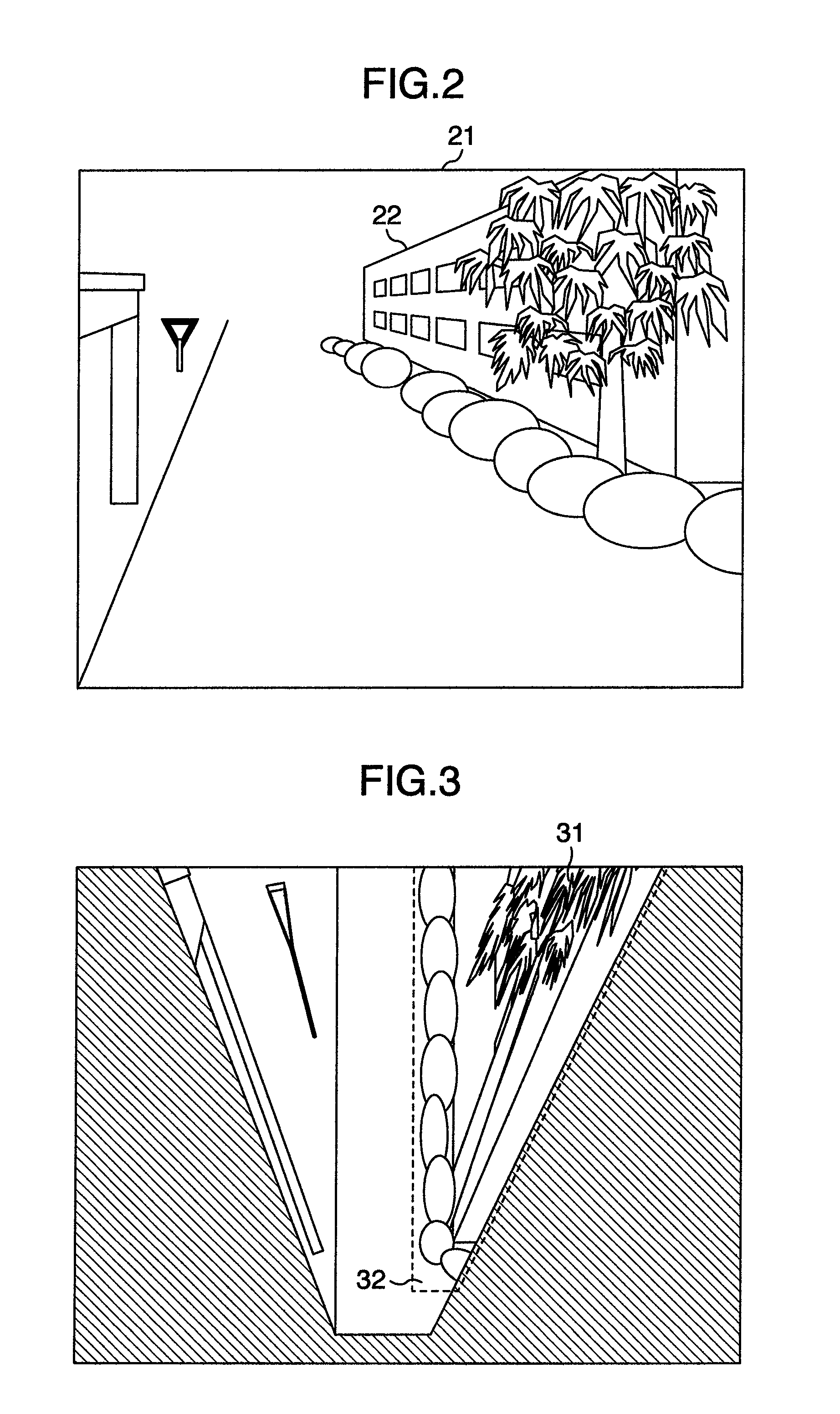
[0113]Referring to FIG. 10, an input image 221 acquired in image input step S201 is illustrated. The input image 221 is displayed on the display unit 10 in process result display step S209. In the input image 221 of FIG. 10, an object 222 such as for example a prominent person required of guard o...

embodiment 3

[0125]In the present embodiment 3, the coordinate system transformation in the monitor apparatus according to the preceding embodiments 1 and 2 is slightly improved so as to be suitable for designation of the size (size parameter) of an object to be detected. In addition, the user is permitted to interactively input coordinate transformation parameters necessary for the coordinate system transformation.

[0126]An example of configuration of a monitor system according to the present example is illustrated in FIG. 12.

[0127]The monitor system of this example comprises an image pickup unit 301, an object detection unit 302, a display unit 303, a setting unit 304, an access line 311 connecting the image pickup unit 1 and the object detection unit 2, an access line 312 connecting the object detection unit 302 and the display unit 303 and an access line 313 connecting the object detection unit 302 and the setting unit 304.

[0128]The image pickup unit 301, comprised of a camera for picking up ...


PUM


Abstract

In an image processing apparatus for processing images, a transformation unit transforms an image on a first coordinate system representing a coordinate system during pickup to an image on a second coordinate system set up on a reference plane, a display unit displays an image transformed by the transformation unit and a reception unit receives setting information a user inputs in accordance with a displayed image on the display unit. For example, in the image processing apparatus, the reception unit receives, as the setting information, information to be used for image processing.

Description

INCORPORATION BY REFERENCE[0001]The present application claims priority from Japanese application JP 2006-341438 filed on Dec. 19, 2006 and JP 2007-284719 filed on Nov. 1, 2007, the contents of which are hereby incorporated by reference into this application.BACKGROUND OF THE INVENTION[0002]The present invention relates to image processing apparatus and more particularly, to an image processing apparatus which visually facilitates setting operation necessary for image processing by making use of the coordinate transformation.[0003]A monitor apparatus has hitherto been used widely in which an input image representing an image of an area to be monitored that is picked up with an image pickup unit mounted with a solid imaging device such as a CCD (Charge Coupled Device) or CMOS (Complementary Metal-Oxide Semiconductor), for example, is processed by means of an image processing unit to automatically detect a given object transcribed in the input image. As an example of the method for au...

Claims


Application Information

Patent Timeline
Patent Type & Authority Patents(United States)
IPC IPC(8): G06K9/00G06K9/36G06K9/32H04N5/225G09G5/00
CPCG06K9/00369G08B13/1968G06K2209/015G06V40/103G06V2201/01
Inventor ITO, WATARUITO, MITSUE
Owner KOKUSA ELECTRIC CO LTD
Why Eureka
Try Eureka