MRI adjustable head coil

a magnetic resonance device and adjustable head coil technology, applied in the field of magnetic resonance device head coil arrangement, can solve problems such as poor signal-to-noise ratio, and achieve the effect of improving the signal-to-noise ratio

Active Publication Date: 2012-05-29
SIEMENS HEALTHCARE GMBH
View PDF10 Cites 47 Cited by
  • Summary
  • Abstract
  • Description
  • Claims
  • Application Information

AI Technical Summary

Benefits of technology

[0007]An object of the present invention is to provide a head coil arrangement that is suitable for a large number of head sizes and still has an improved signal-to-noise ratio.
[0010]The optimal adjustment to the respective head size achieves an improved signal-to-noise ratio since the proximity to the head allows higher signal intensity. This is particularly advantageous in the case of functional imaging since very low signal intensities are used in this sector. Signal losses are thus minimized by the head coil arrangement according to the invention.
[0015]In an advantageous embodiment the housing parts may be at least partially flexible. Flexible housing parts can be used to further improve the adjustment to the received head. For this purpose, the flexible regions may be pressed against a head by a pressing arrangement, in particular pneumatically, by an air cushion or by a spring. If a head is thus introduced into the local coil arrangement, the flexible region or the completely flexible housing part can be pressed close to this specific head by the pressing arrangement. This leads to a further improvement in the adjustment, and therefore to an improved signal-to-noise ratio. As an alternative to a pressing arrangement the flexible regions may be made of viscofoam, in other words a viscoelastic foam. Viscofoam has a tendency to assume a certain form again in each case. This may be used to achieve automatic pressing as it were and therefore adjustment to the corresponding test object.
[0018]For better accessibility to the inside of the head coil arrangement at least one housing part may be removable from the arrangement. For example, one upper housing part or two upper housing parts may be removable, to allow a patient to introduce his or her head into the head coil arrangement with the requisite level of comfort.
[0020]It is possible for the mobility to be achieved purely mechanically and for the components allowing mobility to be activated manually. One advantage of manual operation is that the operator can immediately assess whether the head coil arrangement possibly encloses the patient's head too tightly and then, for example, presses or causes an unpleasant sensation.
[0022]Alternatively, the housing parts can be moved by a gear or a screw mechanism. An easily reachable hand wheel that is provided on the side of the head coil arrangement is then expedient as an actuator for the movable housing parts.

Problems solved by technology

The head coil arrangement is therefore disadvantageously too large for some of the heads that are to be examined, resulting in a large spacing of the individual coils from the test object, i.e. the head, and therefore a poor signal-to-noise ratio.
In particular when developing new head coil arrangements with a relatively large number of individual coils the known construction is problematical due to the multiplication of the receiving channels, since the required individual coils become smaller and an improved signal-to-noise ratio is therefore indispensable in order to attain sufficiently good signal quality.

Method used


Image

  • MRI adjustable head coil
  • MRI adjustable head coil
  • MRI adjustable head coil

Examples


first embodiment

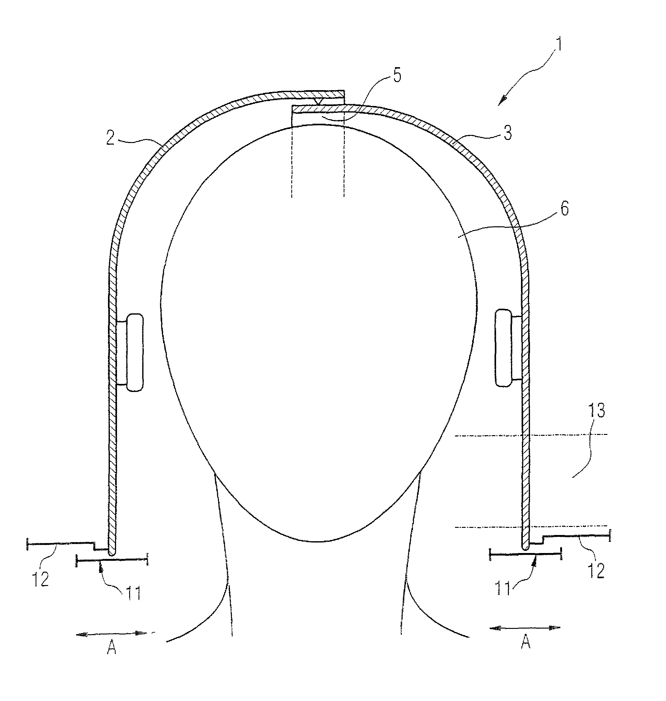
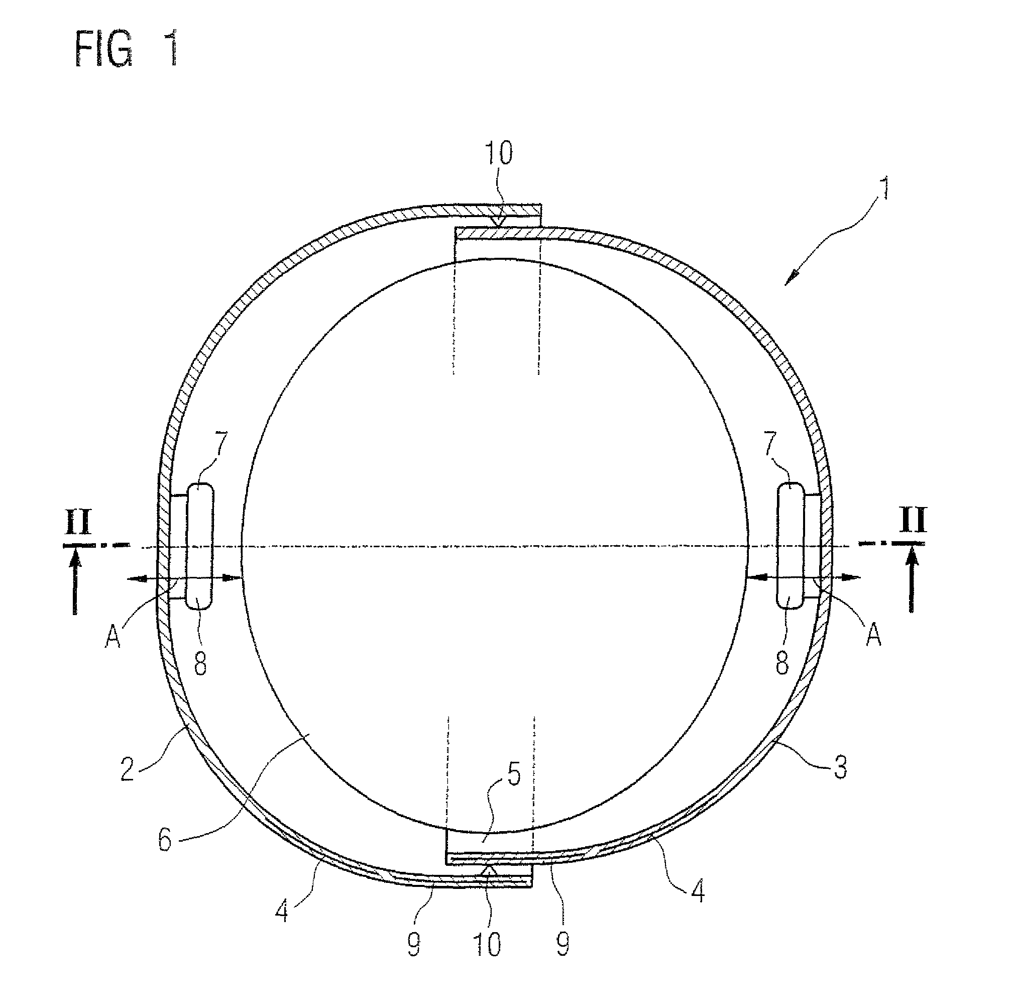
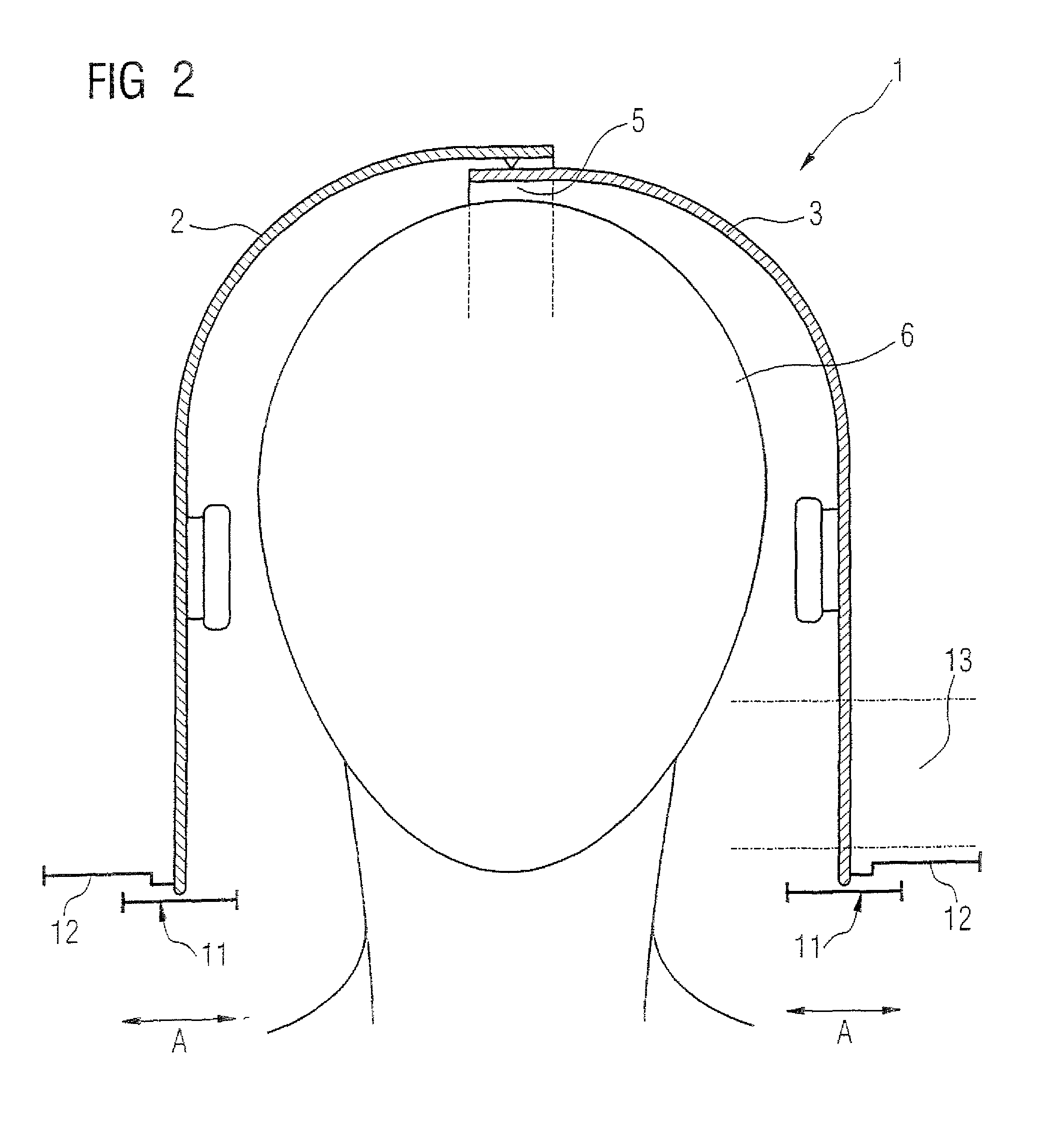
[0036]FIG. 1 shows a vertical section through a head coil arrangement 1 according to a The arrangement 1 has a housing formed by a left housing part 2 and a right housing part 3. The housing parts 2 and 3 are guided in a linear guide (not shown in detail) and can therefore be linearly moved toward each other in the transverse direction of the head, as is indicated by arrow A. Displacement of the housing parts 2 and 3 toward each other is possible by way of manual actuators (not shown in detail), for example a slide or a hand wheel coupled via a gear or screw mechanism. Individual coils 4 that are integrated in the housing parts 2 and 3 are provided which are only partially indicated in FIG. 1.

[0037]The right housing part 3 is designed so it may be introduced into the left housing part 2, whereby an overlapping region 5 is produced. The internal volume of the local coil arrangement 1 becomes smaller by the amount of this overlapping region 5. It is consequently possible to adjust th...

second embodiment

[0042]FIG. 3 shows a vertical section through a head coil arrangement 14 according to a In this case the housing is divided into an upper housing part 15 and a lower housing part 16. The housing parts 15, 16, as indicated by arrow B, can be moved toward each other in the lengthwise direction of the head. For this purpose the housing parts 15, 16 are guided by means of linear guides (not shown in detail) here as well. Again, upon movement of the housing parts 15, 16 toward each other an overlapping region 17 is produced by which the internal volume of the head coil arrangement 14 is reduced, so adjustment to a head 6 (that is shown only schematically) is made possible.

[0043]FIG. 4 shows a vertical section through a head coil arrangement 18 according to a third exemplary embodiment. Here four housing parts 19 that each substantially cover a quarter of the head 6 are provided and these may each be moved in the transverse direction of the head 6, as indicated by arrow C, and in the len...

fourth embodiment

[0045]FIG. 5 shows a vertical section through a head coil arrangement 23. An upper housing part 24 and a lower housing part 25 are again provided here, it being possible for the housing parts 24, 25 to move toward each other in the lengthwise direction of the head 6, as symbolized by the arrow E. In this embodiment the housing parts 24 and 25 have substantially rigid housing part regions 24a, 25a and flexible housing part regions 24b and 25b. The flexible regions 24b and 25b are produced for example from a flexible plastics material. It is also possible to use a viscofoam that allows the flexible regions 24b and 25b to automatically adjust to the shape of the head 6. In this example however press-on elements 26 of which only the basic structure is shown are provided, which may be designed, for example, pneumatically, as air cushions or a spring. The press-on elements 26 press the flexible housing regions 24b and 25b along the arrow F onto the head 6, it being possible to achieve a r...


PUM


Abstract

A head coil arrangement for a magnetic resonance device has a housing on or in which a number of coils are arranged, the housing having at least two housing parts that can be moved toward each other for adjustment to different head sizes.

Description

BACKGROUND OF THE INVENTION[0001]1. Field of the Invention[0002]The present invention relates to a head coil arrangement for a magnetic resonance device, of the type having a housing on or in which a number of coils are arranged.[0003]2. Description of the Prior Art[0004]Head coil arrangements of the above type are known and are used in magnetic resonance devices as radio-frequency transmitting and receiving coils. If the coils operate in a receiving mode, the size of the coils in relation to the size of the test object plays a decisive role in the resulting signal-to-noise ratio. The signal-to-noise ratio is optimal if the coils rest as close as possible to the surface of the examination object, in this case the head.[0005]In the prior art various head coil arrangements are known that are constructed so as to be suitable for at least 95% of all head sizes. By taking account of patient comfort and noise-protection, in particular by allowing space for headphones, a relatively large i...

Claims


Application Information

Patent Timeline
Patent Type & Authority Patents(United States)
IPC IPC(8): A61B5/05
CPCG01R33/3415A61B5/055G01R33/34084A61B5/702
Inventor DRIEMEL, DANIEL
Owner SIEMENS HEALTHCARE GMBH
Why Eureka
Try Eureka