
Apparatus for absorbing acoustical energy and use thereof

a technology of acoustic energy and an apparatus, applied in the field of apparatus for the absorption of acoustic energy, can solve problems such as bad reflected sound, and achieve the effects of reducing the number of components, improving sensitivity, and manufacturing cos

Active Publication Date: 2012-06-05
SE ELECTRONICS INT
View PDF34 Cites 16 Cited by
  • Summary
  • Abstract
  • Description
  • Claims
  • Application Information

AI Technical Summary

Benefits of technology

[0034]As described above, in accordance with the present invention, a center portion of a back electret is subjected to a series of processes such as a pressing to render a surface of a high molecular film of the back electret opposing a diaphragm into a concave surface similar to a vibrating form of the diaphragm so that a conversion of a displacement of the diaphragm to an electrical signal is maximized to improve sensitivity and that the spacer for forming an insulation space is eliminated to reduce the number of components and the manufacturing cost.
[0035]While the present invention has been particularly shown and described with reference to the preferred embodiment thereof, it will be understood by those skilled in the art that various changes in form and details may be effected therein without departing from the spirit and scope of the invention as defined by the appended claims.

Problems solved by technology

However, reflected sound may be considered bad if they distort the recorded sound by making certain notes sound louder while canceling out other sounds.
The recorded sound may result in midrange or high frequencies that are too sharp or harsh or may result in an echo.

Method used


Image

  • Apparatus for absorbing acoustical energy and use thereof
  • Apparatus for absorbing acoustical energy and use thereof
  • Apparatus for absorbing acoustical energy and use thereof

Examples


third embodiment

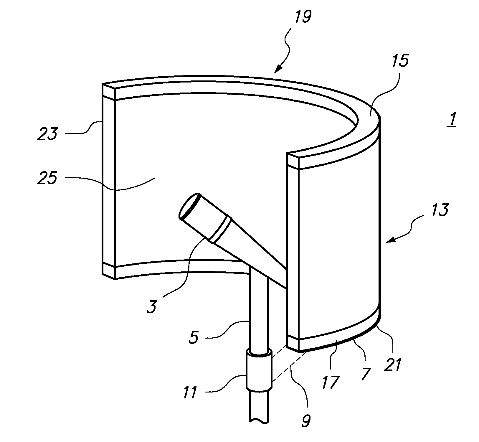
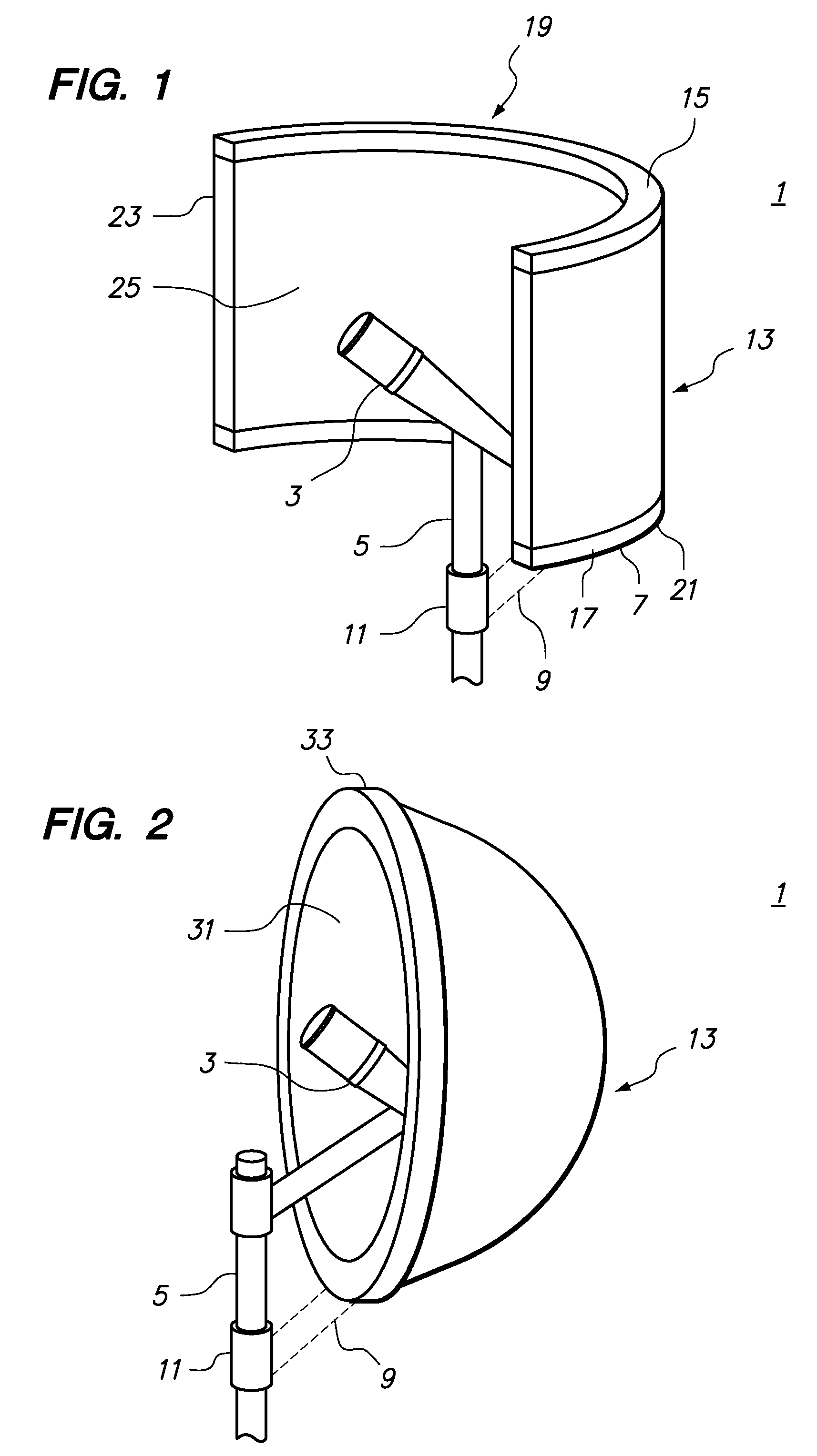
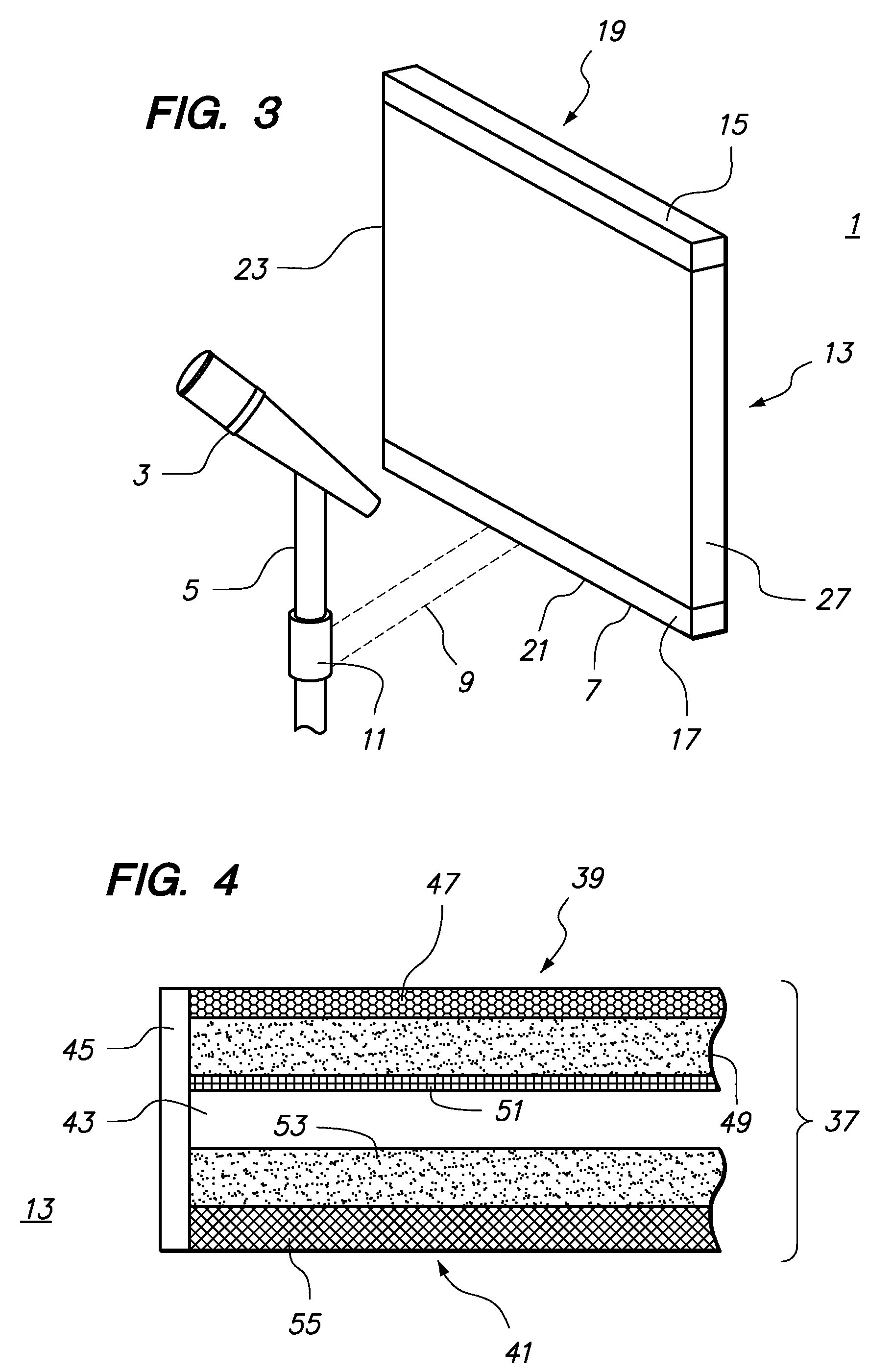
[0046]A third embodiment is shown in FIG. 3, which is again analogous to the embodiment shown in FIGS. 1 and 2 and therefore, identical reference numerals are used for like integers. In this case, the composite acoustically absorbing member 13 is rectangular and substantially flat.

[0047]FIG. 4 shows a partial cross-section though the composite acoustic absorbing member 13 shown in FIG. 3 but it can readily be appreciated that essentially the same layer structure will apply to the embodiments of FIGS. 1 and 2.

[0048]As shown in FIG. 4, the layer structure 37 of the acoustical energy absorbing member 13 comprise a rear solid layer structure 39 and a front solid layer structure 41. These rear and front layer structures 39, 41 are substantially parallel with each other but separated by an air gap 43. The layer structures 39 and 41 with the air gap 43 therebetween are maintained in this position by a peripheral frame member 45.

[0049]The rear layer structure 39 comprises an outer punched a...

fourth embodiment

[0054]A fourth embodiment is shown in FIG. 5, which is analogous to the embodiment shown in FIG. 1, and therefore, identical reference numerals are used for like integers. In this case, as yet an additional sound absorbing layer, a series of flat panels 60 are attached to the concave face 25 by an attachment means holding the flat panels 60 in place such that an additional air gap layer 65 is defined between the concave face 25 of the composite acoustic absorbing structure 13 and each flat panel 60.

[0055]FIG. 6 shows a partial cross section through the acoustical panel shown in FIG. 5. As shown in FIG. 6, an additional air gap layer 65 is defined by the boundaries of each flat panel 60 and the concave face 25 of the composite acoustic absorbing structure 13.

[0056]In the light of the foregoing description of preferred exemplary embodiments, variations, modifications of those embodiments, as well as other embodiments, all within the spirit and scope of the appended claims, will not be...


PUM


Abstract

An apparatus comprising a combination of a microphone and a composite acoustic panel. The composite acoustic panel comprises materials having different spectra of acoustic absorption. The materials may be integrated in a single layer or in a plurality of different layers.

Description

TECHNICAL FIELD[0001]The present invention relates to an apparatus for the absorption of acoustical energy. Specifically, the present invention relates to an acoustic panel of a shape engineered for a particular use, and acoustical panels of a particular composition of layered material.BACKGROUND ART[0002]Acoustic panels have long been used to change the acoustic qualities of a particular space, such as a room, or a professional environment, for example a studio, auditorium, theater or stadium. The primary use of acoustic panels is in professional environments, where the acoustical characteristics are sufficiently critical to require extraordinary treatment and use of specialized devices to achieve the acoustic quality. However, many uses of acoustical panels now include interior and exterior locations in homes, offices and commercial spaces where acoustical characteristics are not as critical as in a professional environment.[0003]The sound that is received through a device that co...

Claims


Application Information

Patent Timeline
Patent Type & Authority Patents(United States)
IPC IPC(8): E04B1/82
CPCG10K11/168H04R1/342
Inventor ZOU, SIWEI
Owner SE ELECTRONICS INT
Learn More