Actuator

a technology of actuators and actuators, applied in the field of actuators, can solve problems such as harmonic gear jamming, actuator can typically continue to operate in a number of failure conditions

Active Publication Date: 2012-06-05
AIRBUS OPERATIONS LTD
View PDF19 Cites 6 Cited by
  • Summary
  • Abstract
  • Description
  • Claims
  • Application Information

AI Technical Summary

Benefits of technology

[0012]The actuator can typically continue to operate in a number of failure conditions including failure of one of the motors, jamming of a drive path between one of the motors and the output member, and jamming of the harmonic gear. The harmonic gear provides various advantages compared with planetary gears including: high gearing ratio combined with a low weight; compact size, particularly in the axial direction; low backlash; and low moment of inertia.
[0014]The actuator may further comprise two brakes, each configured to apply a braking force to a respective one of the harmonic gear components, either by engaging the component or by engaging an element in the drive path associated with that harmonic gear component. This enables the actuator to be operated in a mode in which one of the motors is supplying power (or is shorted so as to generate a damping force) and the other is locked by the brake.
[0016]Typically the gear ratio between the output member and the first motors is different to the gear ratio between the output member and the second motors. This enables dissimilar motors to be used, which are less likely to fail at the same time than similar motors.

Problems solved by technology

The actuator can typically continue to operate in a number of failure conditions including failure of one of the motors, jamming of a drive path between one of the motors and the output member, and jamming of the harmonic gear.

Method used


Image

  • Actuator
  • Actuator
  • Actuator

Examples


Embodiment Construction

)

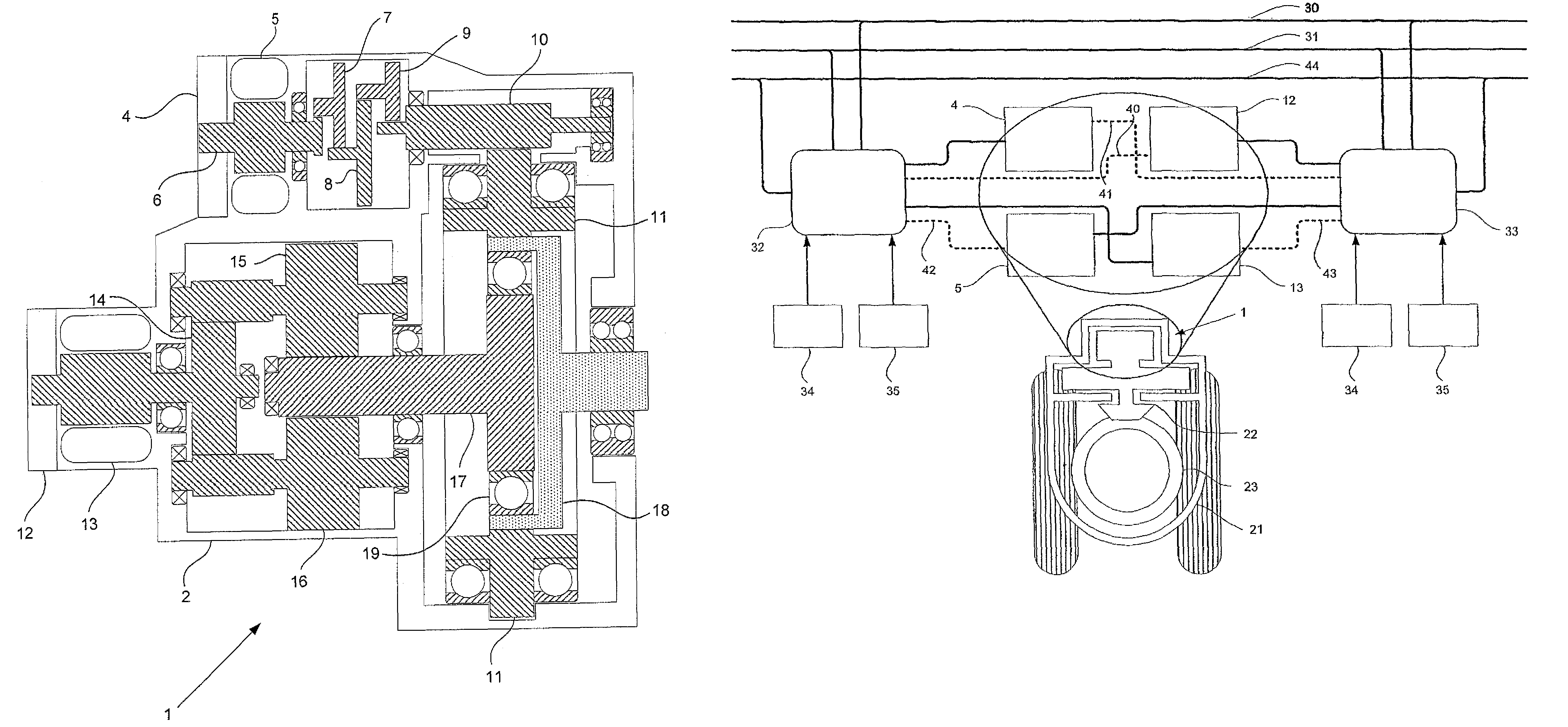
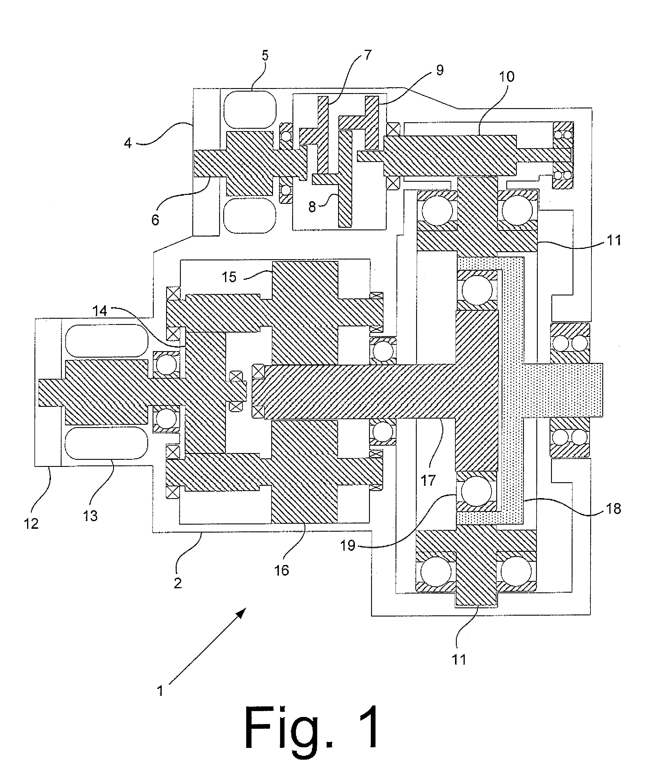
[0031]Referring to FIG. 1, an actuator 1 is shown. The actuator comprises a housing 2, and comprises a high rate drive path and a high torque drive path each coupled to a common output member. The high rate drive path comprises a brake 4, an electric motor 5, a high rate gearbox comprising a set of five interlocking gears 6-10 and a circular spline 11. The high torque drive path comprises a brake 12, an electric motor 13, a high torque gearbox comprising three gears 14-16, and a wave generator 17.

[0032]The high rate drive path and high torque drive path operate in parallel, and both couple to a flexspline 18 with a shaft protruding from the housing which acts as the output member of the actuator. When the two drive paths are driven to deliver the same mechanical power, the motor 5 in the high rate path rotates at a significantly greater speed than the motor 13 in the high torque path. For example the gear ratio of the high rate path may be 1600:1 and the gear ratio of the high torq...


PUM


Abstract

An actuator comprising: two motors; an output member; and a harmonic gear comprising: an elliptical wave generator component; a flexible spline component which is coupled to the wave generator by a bearing and flexes to conform to the elliptical shape of the wave generator; and a circular spline component which surrounds and meshes with the flexible spline component. One of the harmonic gear components is coupled to the output member, and each of the other harmonic gear components is coupled to a respective one of the motors.

Description

[0001]This application is the U.S. national phase of International Application No. PCT / GB2007 / 050532, filed 11 Sep. 2007, which designated the U.S. and claims priority to Great Britain Application No. 0618902.1, filed 25 Sep. 2006, the entire contents of each of which are hereby incorporated by reference.FIELD OF THE INVENTION[0002]The present invention relates to an actuator with two motors driving a common output member.BACKGROUND OF THE INVENTION[0003]An actuator of this kind is described in US2005 / 0229729. The motors are coupled to the output member by a planetary differential reduction gear. The output member is driven by only one of the motors, should the other motor break down. The actuator is used to lock the undercarriage of an aircraft in a retracted position.SUMMARY OF THE INVENTION[0004]A first aspect of the invention provides an actuator comprising:[0005]a high rate drive path including a first motor and a high rate gearbox;[0006]a high torque drive path including a sec...

Claims


Application Information

Patent Timeline
Patent Type & Authority Patents(United States)
IPC IPC(8): B64C25/50
CPCB64C25/505F16H37/065F16H49/001Y10T74/2184Y10T74/19637Y10T74/19
Inventor KNIGHT, MATTHEW JOHN
Owner AIRBUS OPERATIONS LTD
Why Eureka
Try Eureka