Installation for the manufacture of containers from a preform and method of controlling the blow-molding means of such an installation

a technology of installation and manufacturing method, which is applied in the direction of domestic applications, hollow objects, other domestic objects, etc., can solve the problems of airborne particle contamination of empty mold, contaminating the interior of mold, and inacceptable contamination risks, and achieves a simple and economical way of combating contamination

Inactive Publication Date: 2012-06-05
SIDEL PARTICIPATIONS SAS
View PDF13 Cites 12 Cited by
  • Summary
  • Abstract
  • Description
  • Claims
  • Application Information

AI Technical Summary

Benefits of technology

[0028]To this end, the invention proposes a method of controlling an installation for manufacturing containers, in particular bottles, by blow-molding or by stretch-blow-molding from a thermoplastic material form, the installation including at least one molding unit equipped with a control device adapted to control movement of at least one blow-molding or stretch-blow-molding nozzle which is associated with a mold, in which the nozzle is mounted to be mobile vertically between a top position and a bottom position in which, the mold being in a closed position, the nozzle caps at least one orifice for the neck of the preform that includes a top horizontal wall of the mol

Problems solved by technology

This is why there is a risk of airborne particle contamination of the empty mold, in particular by germs, bacteria, etc. present in the surrounding atmosphere and liable to contaminate the interior of the mold and consequently preforms and containers subsequent

Method used


Image

  • Installation for the manufacture of containers from a preform and method of controlling the blow-molding means of such an installation
  • Installation for the manufacture of containers from a preform and method of controlling the blow-molding means of such an installation
  • Installation for the manufacture of containers from a preform and method of controlling the blow-molding means of such an installation

Examples


Embodiment Construction

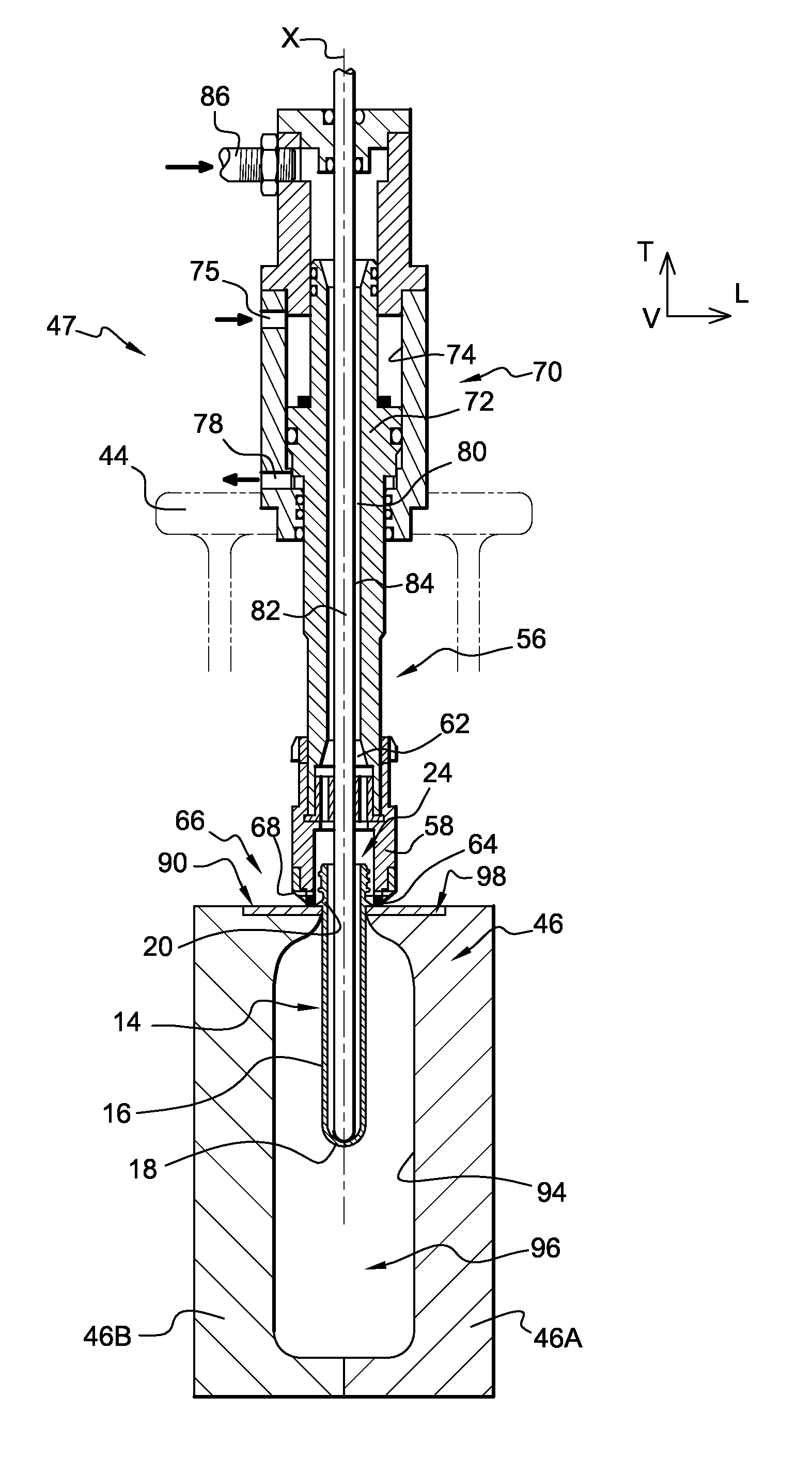
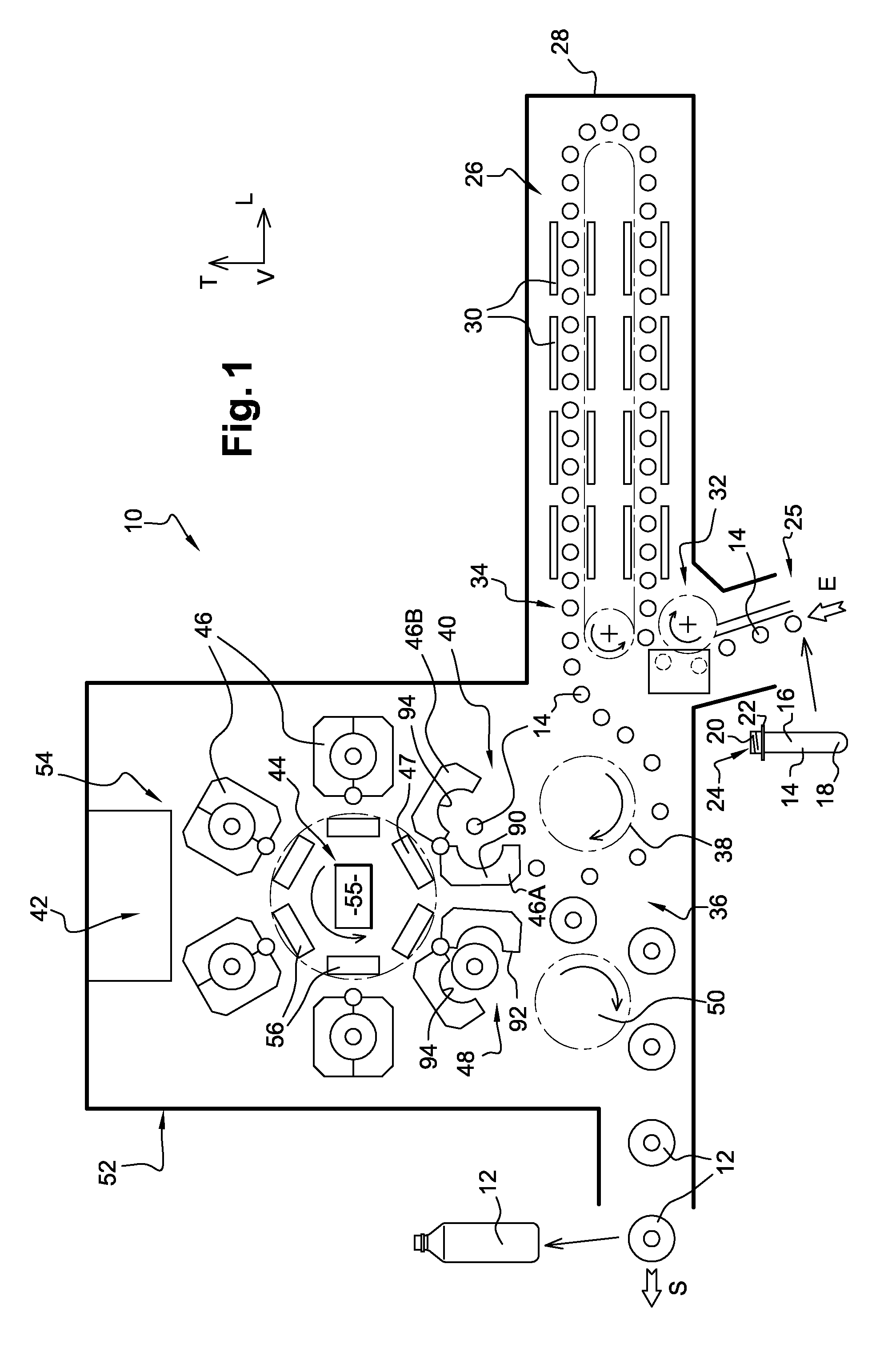
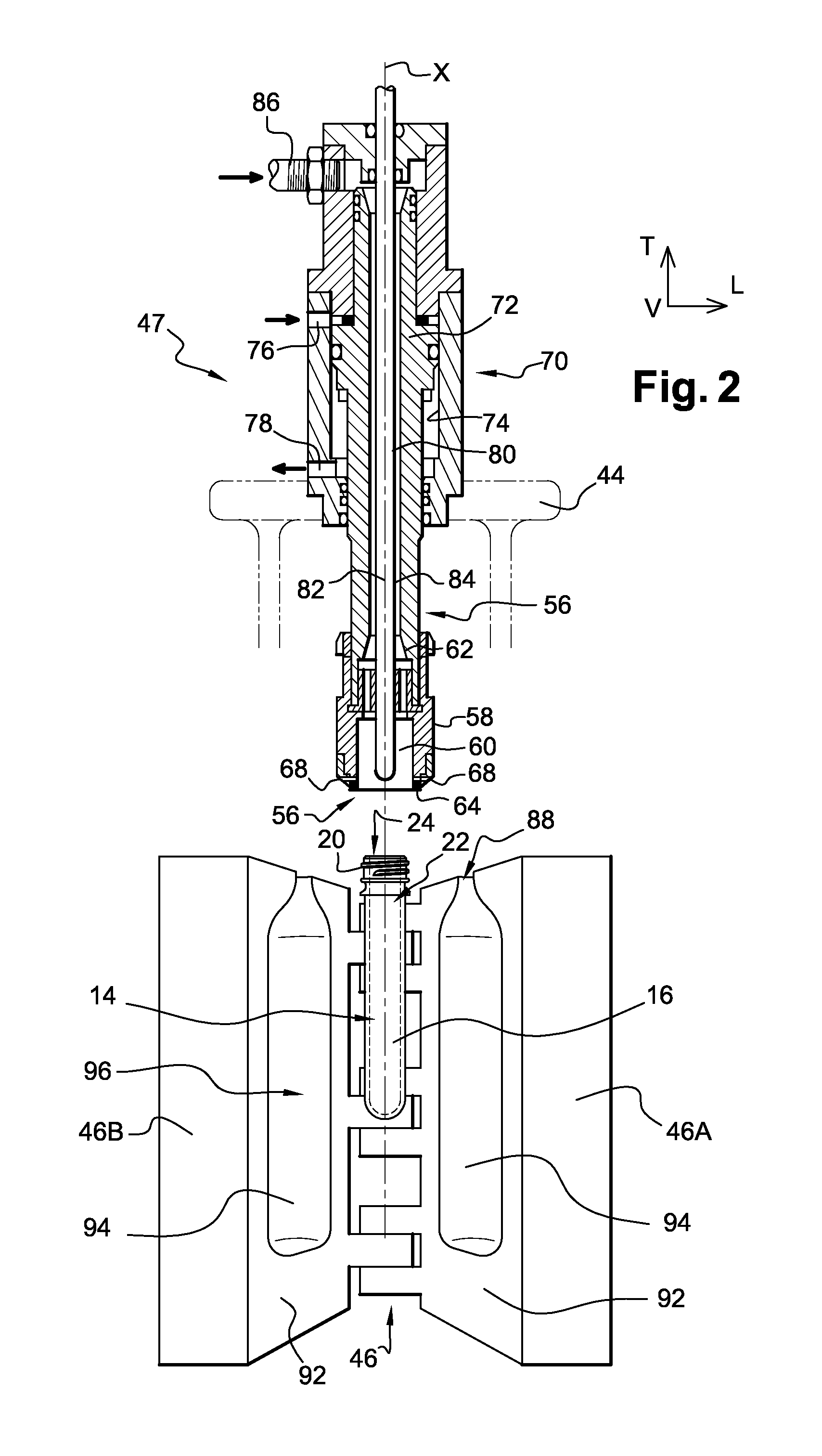
[0046]In the description and the claims the terms “top” and “bottom”, etc. and the orientations “longitudinal”, “vertical” and “transversal” are used in a nonlimiting way to designate elements according to the definitions given in the description and to the axes (L, V, T) represented in the figures.

[0047]FIG. 1 represents diagrammatically an installation 10 for the manufacture of containers 12, in particular bottles, by blow-molding or by stretch-blow-molding from a preform 14 in thermoplastic material, for example PET (polyethylene terephthalate).

[0048]FIG. 1 shows in detail one embodiment of a preform 14, sometimes called a blank, for the manufacture of a hollow body container, such as a bottle, a flask, etc., advantageously by a transformation method employing blow-molding or stretch-blow-molding.

[0049]By definition, in the remainder of the present description the term “container” designates either the finished container, such as the bottle shown in detail in FIG. 1, which is for...


PUM

PropertyMeasurementUnit
Pressureaaaaaaaaaa

Abstract

An installation for manufacturing containers by moulding from a perform includes at least one moulding unit having a control device for controlling at least one nozzle associated with a mould, the nozzle being vertically movably mounted so as to move vertically between a top position and a bottom position in which the mould is closed. The nozzle covers at least one flow opening that includes an upper horizontal wall of the mould. The manufacture involves at least a first step including, the mould being closed, systematically controlling the vertical descent of the nozzle towards the bottom position independently of the presence or absence of a preform in the mould so that, both when the installation is operating and when it is at rest, the internal volume of the mould is isolated in order to avoid the risk of airborne particulate contamination.

Description

BACKGROUND OF THE INVENTION[0001]1. Field of the Invention[0002]The present invention concerns an installation for the manufacture of containers from a preform and a method of controlling blow-molding means of such an installation.[0003]The invention concerns more particularly an installation for manufacturing containers, in particular bottles, by blow-molding or by stretch-blow-molding from a thermoplastic material preform, the installation including at least:[0004]a preform feeding device adapted to feed an entry of the installation with preforms,[0005]a thermal conditioning unit including at least one oven including means for heating preforms arranged between an entry area to which the preforms are fed by the feed device and an exit area which opens into a transfer area of the installation,[0006]a first transfer device in the transfer area adapted to transfer thermally conditioned preforms from the exit area of the oven to a feeding area of a molding unit,[0007]the molding unit i...

Claims


Application Information

Patent Timeline
IPC IPC(8): B29C49/08B29C49/78
CPCB29C49/58B29C49/78B29C49/12B29K2067/00B29C2049/78765
Inventor ADRIANSENS, ERIC
Owner SIDEL PARTICIPATIONS SAS
Why Eureka
Try Eureka