Method and arrangement for winding a winding wire onto a winding body and associated magnet assembly for a solenoid valve

a technology of winding wire and solenoid valve, which is applied in the direction of valves, mechanical devices, transformers/inductance coils/windings/connections, etc., can solve the problems of shrinkage and water absorption, process influences after injection molding, and shearing of insulation, etc., to increase process reliability, less cross section, and the effect of increasing the process reliability

Active Publication Date: 2012-06-05
ROBERT BOSCH GMBH
View PDF11 Cites 5 Cited by
  • Summary
  • Abstract
  • Description
  • Claims
  • Application Information

AI Technical Summary

Benefits of technology

[0011]In an embodiment of the arrangement according to the invention, a cutting-and-stamping die is provided, which is embodied so as to cut off a winding wire end, which after the winding procedure, has been threaded into a second wire-receiving slot and rests against a second wire support situated after the second wire-receiving slot, and so as to reshape the winding wire in a region resting on the second wire support in such a way that the diameter of the winding wire in this region is enlarged in the direction of the width of the second wire-receiving slot in order to prevent the winding wire end from slipping back into the second wire-receiving slot. For the reshaping of the region of the threaded winding wire resting on the first wire support, the holding-and-stamping die has, for example, a first stamping protrusion that presses the winding wire into a first recess in the first wire support. The cutting-and-stamping die additionally has a second stamping protrusion that presses against the region of the threaded winding wire, which is resting on the second wire support, into a second recess in the second wire support in order to execute the reshaping. The recesses in the wire supports are embodied, for example, in the form of notches that each have a stamping edge that is situated directly behind the respective wire-receiving slot and bends the winding wire. The recesses embodied in the fond of notches, the holding-and-stamping die, the cutting-and-stamping die, and the stamping edges are embodied so that the shapes of the winding wire beginning and the winding wire end remain essentially unchanged. This advantageously assures a wire remnant-free winding, i.e. the winding wire end remaining in the wire guide of the winding machine is not bent and can thus be used as the winding wire beginning of the next winding support in the next winding process. The plastic reshaping of the winding wire in the region of the recesses and the bending of the winding wire by means of the stamping edges on the one hand prevents the back-slippage into the corresponding wire-receiving slot and on the other hand, the winding wire is deformed less in cross section, thus making it possible to facilitate the testing for the presence and spacing of the winding wire in a testing window of a subsequent camera testing and to prevent the occurrence of pseudo-errors in camera testing caused by reduced winding wire cross sections. In addition, the invention also makes it possible to reduce the volume of rejects in the manufacture of magnet assemblies.

Problems solved by technology

Since the electrical connection dome is embodied in the form of an injection-molded plastic part, it is difficult, from an injection molding standpoint, to maintain the required tolerance for the slot width.
In addition, process influences after the injection molding, such as shrinkage and water absorption are not, as a rule, taken into account in the component measurements.
This can result in an incorrect positioning of the winding wire in which the contacting region toward the cutting blade is no longer present or under some circumstances, lies outside the contacting zone in the region of the cutting blade opening.
In addition, a potential excessive back-slippage of the winding wire can result in a contact between the winding wire and the housing casing of the magnet assembly.
Vibrations that occur with field loading can result in a shearing-through of the insulation of the winding wire and thus to a short-circuiting and therefore also a failure of the magnet assembly.

Method used


Image

  • Method and arrangement for winding a winding wire onto a winding body and associated magnet assembly for a solenoid valve
  • Method and arrangement for winding a winding wire onto a winding body and associated magnet assembly for a solenoid valve
  • Method and arrangement for winding a winding wire onto a winding body and associated magnet assembly for a solenoid valve

Examples


Embodiment Construction

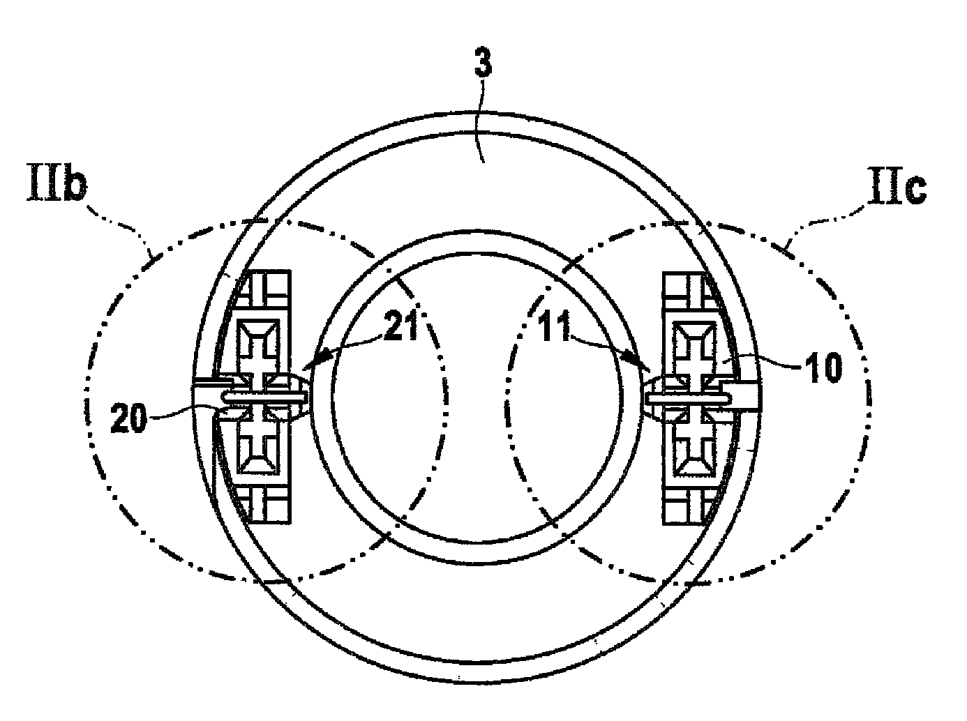
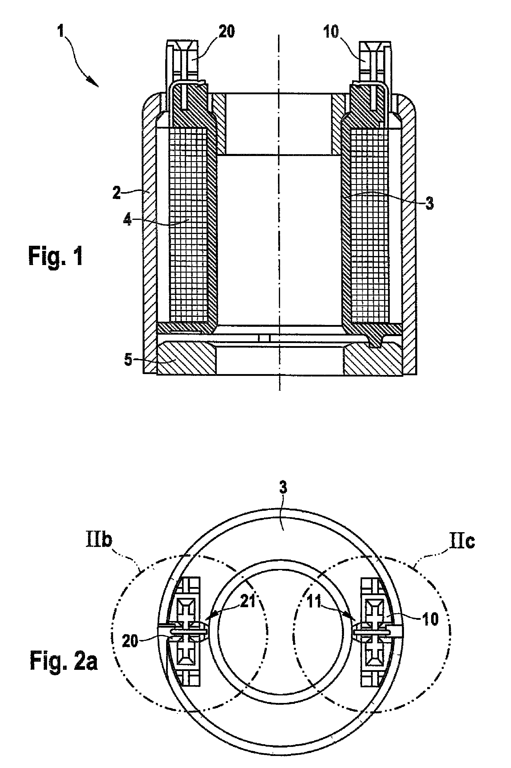
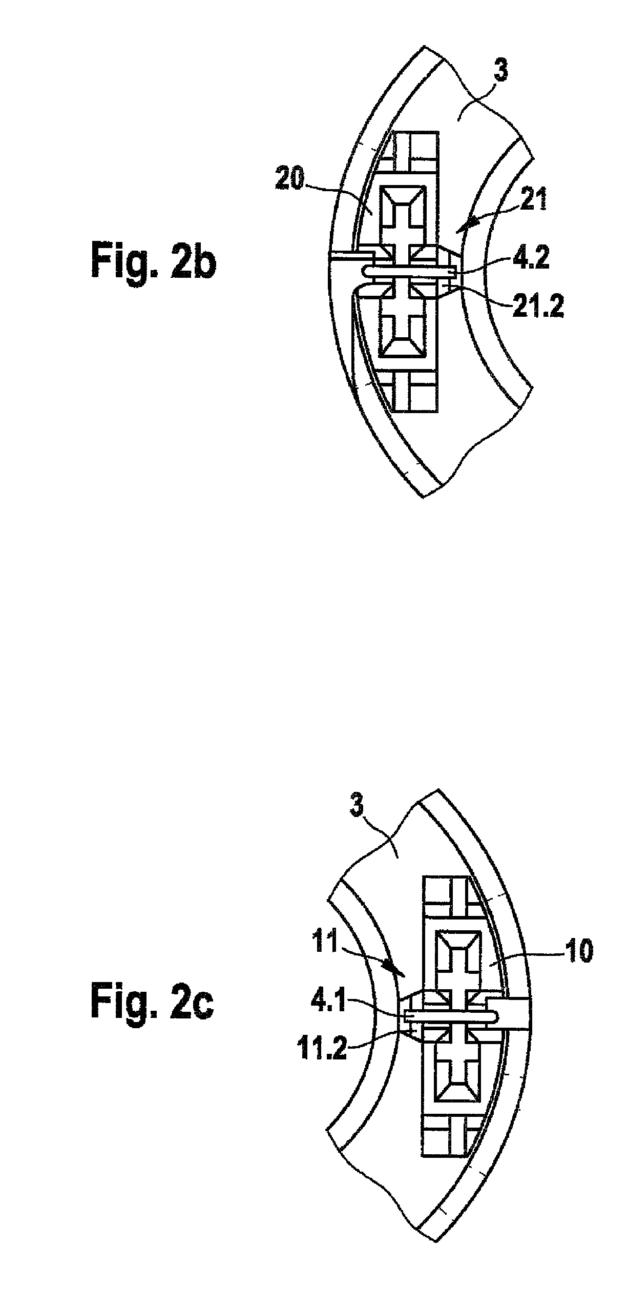
[0024]As shown in FIGS. 1 through 3b, a magnet assembly 1 for a solenoid valve includes a winding body 3 that has a first electrical connection dome 10, which is equipped with a first wire-receiving slot 12 embodied in the form of a cutting-and-clamping connection 13 into which slot a winding wire beginning 4.1 is threaded, and a second electrical connection dome 20, which is equipped with a second wire-receiving slot 22 embodied in the form of a cutting-and-clamping connection 23 into which slot a winding wire end 4.2 is threaded. A magnetic circuit of the magnet assembly 1 is formed by a housing casing 2 and a covering disk 5 that is press-fitted into the housing casing 2. The electrical connection domes 10, 20 are embodied, for example, in the form of injection-molded plastic parts. As is also shown in FIGS. 2a through 2c, the first electrical connection dome 10 and the second electrical connection dome 20 each have a respective wire support 11, 21 equipped with a respective firs...


PUM

PropertyMeasurementUnit
diameteraaaaaaaaaa
shapeaaaaaaaaaa
shapesaaaaaaaaaa

Abstract

The invention relates to a method and an arrangement for winding a winding wire onto a winding body, and to an associated magnet assembly. The start of the winding wire is threaded into a first wire-receiving slot of a first electrical connection dome. By a winding operation a predefinable number of turns are then wound onto the winding body, and one end of the winding wire is threaded into a second wire-receiving slot of a second electrical connection dome and cut off. According to the invention, the start of the winding wire which has been threaded into the first wire-receiving slot is placed on a first wire support which is arranged downstream of the first wire-receiving slot. The winding wire is shaped and held before the winding operation such that the diameter of the winding wire is increased at one region positioned on the first wire support, in the direction of the width of the first wire-receiving slot, and the start of the winding wire is prevented from slipping back into the first wire-receiving slot.

Description

CROSS-REFERENCE TO RELATED APPLICATION[0001]This application is a 35 USC 371 application of PCT / EP2008 / 058777 filed on Jul. 7, 2008.BACKGROUND OF THE INVENTION[0002]1. Field of the Invention[0003]The invention relates to a method for winding a winding wire onto a winding body, an arrangement for winding a winding wire onto a winding body, and an associated magnet assembly for a solenoid valve.[0004]2. Description of the Prior Art[0005]In modern brake systems and driver assist systems, which include for example an antilock brake system (ABS), a traction control system (TCS), or an electronic stability program system (ESP system), solenoid valves are used for pressure modulation. Broken down roughly into their basic components, these solenoid valves are composed of a valve cartridge that is calk-mounted in a fluid assembly, and a magnet assembly installed as a rule in an associated control unit. The magnet assembly is activated with electrical activation signals in order to produce a ...

Claims


Application Information

Patent Timeline
Patent Type & Authority Patents(United States)
IPC IPC(8): F16K31/02H01F27/28B21D11/14
CPCH01F5/02H01F41/0666H01F2007/062H01F41/076
Inventor GONZALEZ ROMERO, RAFAELKELLNER, BERND
Owner ROBERT BOSCH GMBH
Why Eureka
Try Eureka