
Display apparatus, driving method for display apparatus and electronic apparatus

Active Publication Date: 2012-06-12
JOLED INC
View PDF9 Cites 0 Cited by
  • Summary
  • Abstract
  • Description
  • Claims
  • Application Information

AI Technical Summary

Benefits of technology

[0017]In the display apparatus, within the writing period from the first timing at which the potential of the signal line changes over from the reference potential to the signal potential to the second timing at which the sampling transistor is placed into an off state in response to the control signal, the signal potential is written into the storage capacitor. Thereupon, the signal selector variably controls the first timing in response to the signal potential thereby to variably control the writing period from the first timing to the second timing. Within this writing period, the driving current flowing through the driving transistor is negatively fed back to the storage capacitor to carry out correction against the dispersion of the mobility of the driving transistor. Therefore, the writing period from the first timing to the second timing serves as the mobility correction period. In the present embodiment, this writing period, that is, the mobility correction period, is adaptively adjusted in response to the signal potential. Consequently, optimum control of the mobility correction period in accordance with the level or gradation of the signal potential can be achieved, and uniformity of the screen image can be enhanced.

Problems solved by technology

Consequently, the emission light luminance disperses for each pixel, and uniformity of the screen image cannot be obtained.
However, it is known that the optimum mobility correction period is not necessarily fixed but relies upon the gradation level of the image signal.
However, the existing display apparatus does not include a countermeasure in this regard and cannot carry out accurate and complete mobility correction, and therefore has a subject to be solved in that the uniformity of the screen image is not always high.

Method used


Image

  • Display apparatus, driving method for display apparatus and electronic apparatus
  • Display apparatus, driving method for display apparatus and electronic apparatus
  • Display apparatus, driving method for display apparatus and electronic apparatus

Examples


Embodiment Construction

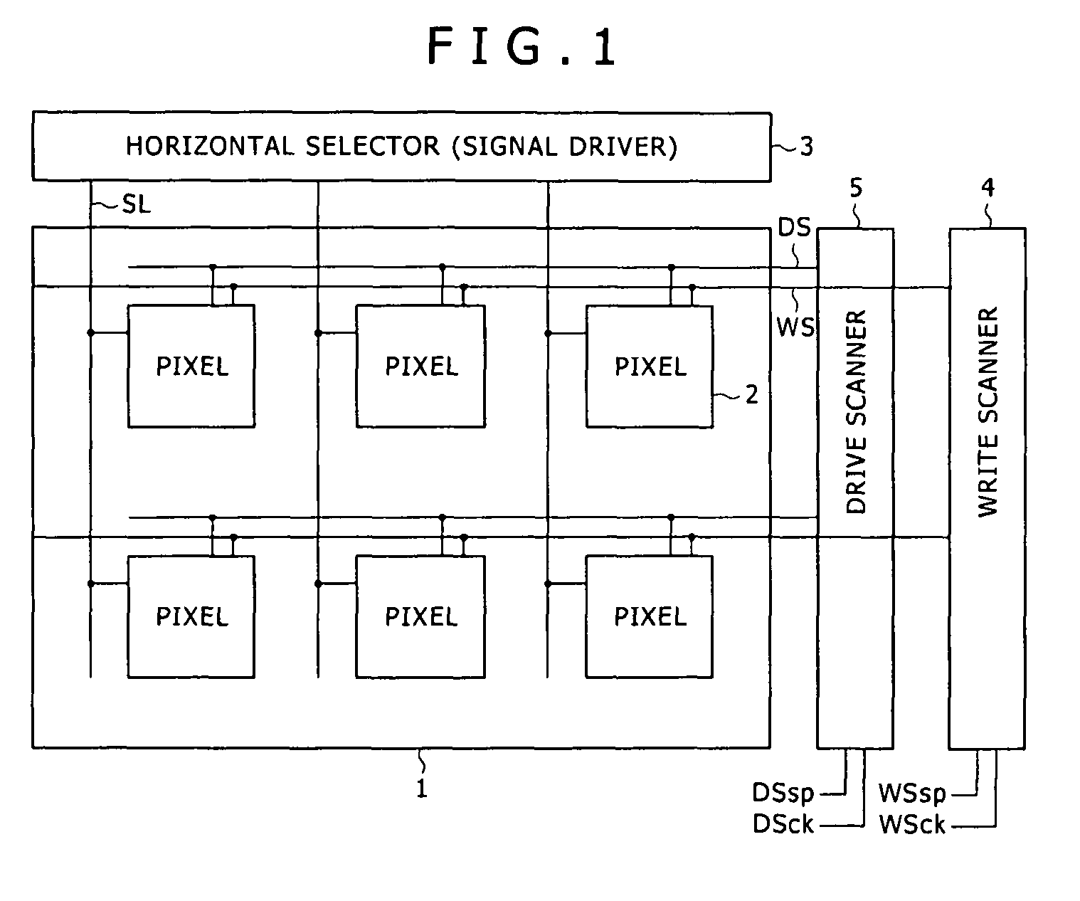
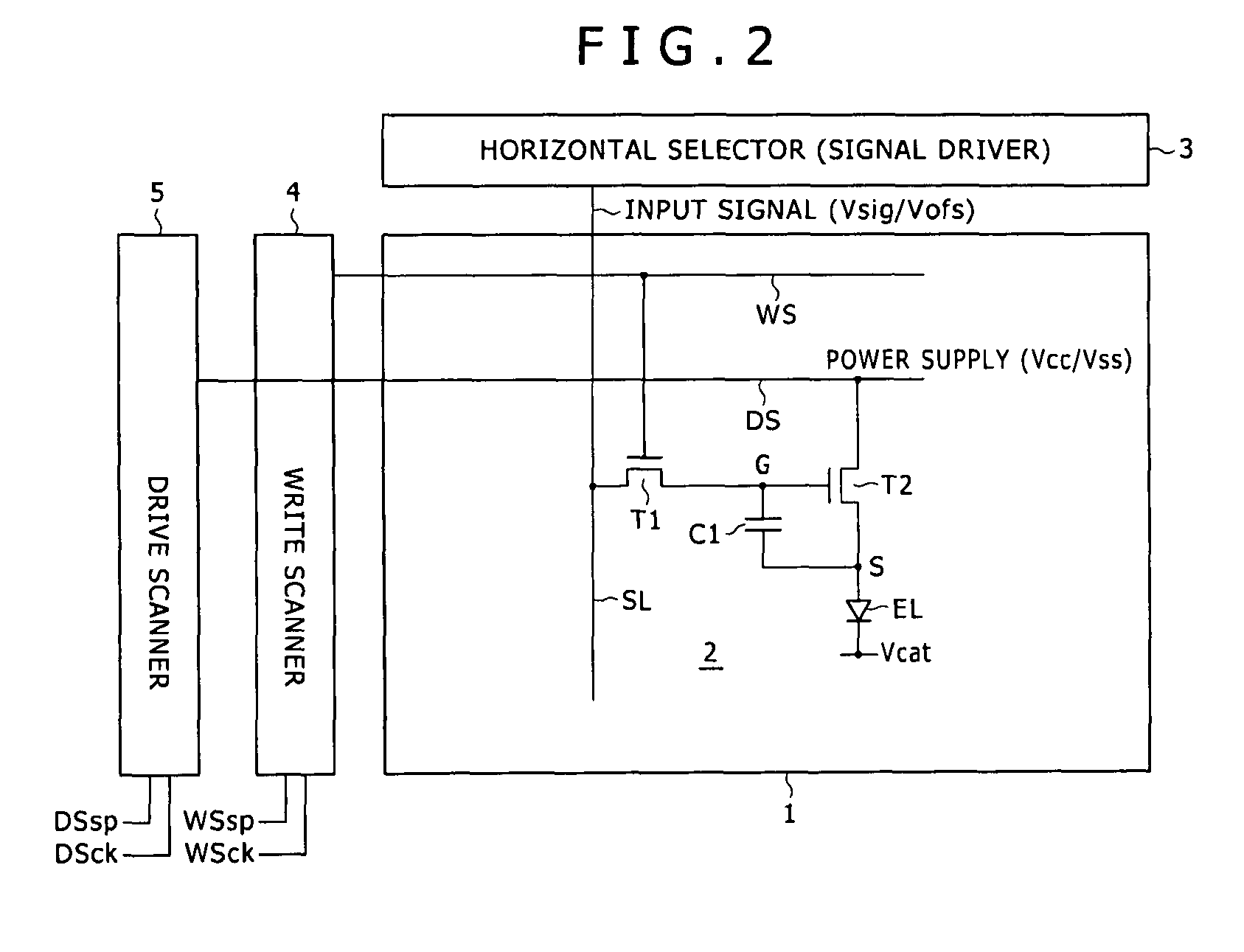
[0042]The preferred embodiment of the present invention will now be described in reference to the accompanying drawings. In the FIG. 1, there is shown a general configuration of a display apparatus according to the embodiment. The display apparatus shown is formed from a panel wherein a pixel array section 1 and driving sections (3, 4 and 5) for driving the pixel array section 1 are formed on the same substrate. The pixel array section 1 includes a plurality of scanning lines WS extending along the direction of a row, a plurality of signal lines SL extending along the direction of a column, a plurality of pixels 2 disposed in rows and columns at places at which the scanning lines WS and the signal lines SL intersect with each other, and a plurality of feed lines DS serving as power supply lines disposed corresponding to the rows of the pixels 2. The driving sections 3, 4 and 5 include a controlling scanner (write scanner) 4 for successively supplying a control signal to the scanning...


PUM


Abstract

The present invention provides a display apparatus, includes: a pixel array section; and a driving section; the pixel array section including a plurality of scanning lines extending along the direction of a row, a plurality of signal lines extending along the direction of a column, and a plurality of pixels disposed in rows and columns at places at which the scanning lines and the signal lines intersect with each other. The driving section including a write scanner and a signal selector.

Description

CROSS REFERENCES TO RELATED APPLICATIONS[0001]The present invention contains subject matter related to Japanese Patent Application JP 2007-304616, filed in the Japan Patent Office on Nov. 26, 2007, the entire contents of which being incorporated herein by reference.BACKGROUND OF THE INVENTION[0002]1. Field of the Invention[0003]This invention relates to a display apparatus of the active matrix type wherein a light emitting element is used in a pixel and a driving method for a display apparatus of the type described. The present invention relates also to an electronic apparatus which includes a display apparatus of the type described.[0004]2. Description of the Related Art[0005]In recent years, development of a display apparatus of the planar self-luminous type which uses an organic EL (electroluminescence) device as a light emitting element is proceeding energetically. The organic EL device utilizes a phenomenon that, if an electric field is applied to an organic thin film, then the...

Claims


Application Information

Patent Timeline
IPC IPC(8): G06F3/038
CPCG09G3/3233G09G2300/0819G09G2300/0842G09G2300/0866G09G2310/0256G09G2320/043H01J37/2955
Inventor YAMAMOTO, TETSUROUCHINO, KATSUHIDETOYOMURA, NAOBUMI
Owner JOLED INC
Features
  • Generate Ideas
  • Intellectual Property
  • Life Sciences
  • Materials
  • Tech Scout
  • Unparalleled Data Quality
  • Higher Quality Content
  • 60% Fewer Hallucinations
Learn More