True time delay photonic circuit

Active Publication Date: 2012-06-12
LOCKHEED MARTIN CORP
View PDF6 Cites 13 Cited by
  • Summary
  • Abstract
  • Description
  • Claims
  • Application Information

AI Technical Summary

Benefits of technology

[0005]Described are systems and methods that provide tunable true time delay of a signal using a compact photonic circuit. The photonic circuit comprises a plurality of waveguides, in which each waveguide corresponds to a differen

Problems solved by technology

While this approach is simple from the perspective of controlling fiber lengths, extreme burden is placed on design and fabrication of the

Method used


Image

  • True time delay photonic circuit
  • True time delay photonic circuit
  • True time delay photonic circuit

Examples


Embodiment Construction

[0021]In the following detailed description, numerous specific details are set forth to provide a full understanding of the present invention. It will be obvious, however, to one ordinarily skilled in the art that the present invention may be practiced without some of these specific details. In other instances, well-known structures and techniques have not been shown in detail to avoid obscuring concepts of the present invention.

[0022]Reference will now be made in detail to aspects of the subject technology, examples of which are illustrated in the accompanying drawings, wherein like reference numerals refer to like elements throughout.

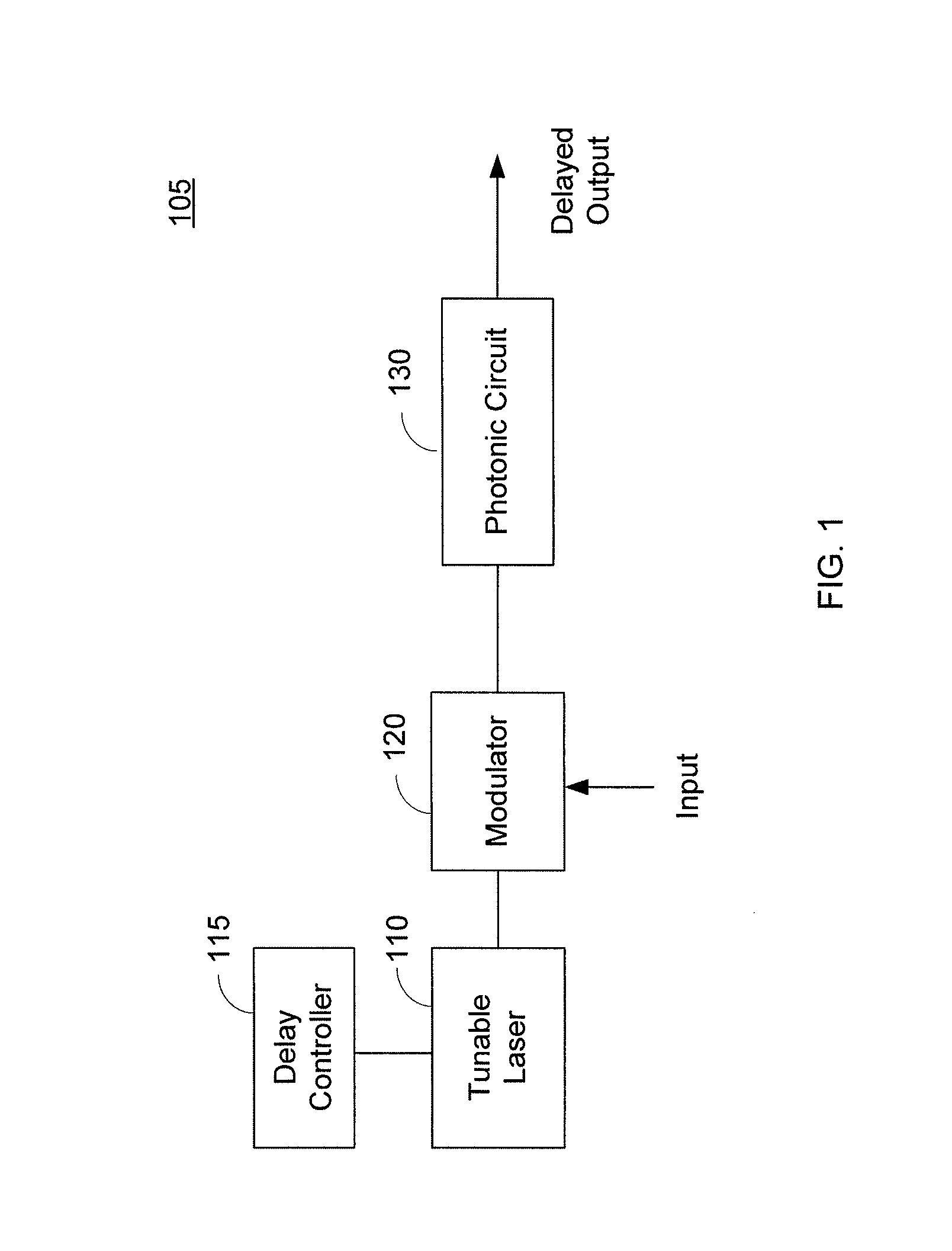
[0023]FIG. 1 illustrates a true time delay system 105 according to an aspect of the present disclosure. The true time delay system 105 comprises a tunable laser 110, a delay controller 115, an optical modulator 120, and a photonic circuit 130.

[0024]The tunable laser 110 is configured to produce an optical carrier signal having a tunable wavelength. Th...


PUM


Abstract

Described are systems and methods that provide tunable true time delay of a signal using a compact photonic circuit. The photonic circuit comprises a plurality of waveguides, in which each waveguide corresponds to a different time delay. A particular one of the waveguides corresponding to a desired time delay is selected by tuning the wavelength of a tunable laser. Additional photonic circuits can be used to provide additional selectable time delays.

Description

RELATED APPLICATION[0001]The present application claims the benefit of priority under 35 U.S.C. §119 from U.S. Provisional Patent Application Ser. No. 61 / 054,446, entitled “TRUE TIME DELAY PHOTONIC CIRCUIT,” filed on May 19, 2008, which is hereby incorporated by reference in its entirety for all purposes.STATEMENT REGARDING FEDERALLY SPONSORED RESEARCH OR DEVELOPMENT[0002]Not Applicable.FIELD OF THE INVENTION[0003]The present invention generally relates to photonic circuits and, in particularly, relates to true time delay photonic circuits.BACKGROUND OF THE INVENTION[0004]One approach to providing true time delay hardware involves using a plurality of low-loss fiber optic waveguides, in which the length of each fiber optic waveguide is configured to achieve a particular delay. A large N×M switch matrix is used to couple light into one of the fiber optic waveguides based on a desired time delay. While this approach is simple from the perspective of controlling fiber lengths, extreme ...

Claims


Application Information

Patent Timeline
IPC IPC(8): G02F1/01G02B6/26G02B6/42G02B6/12
CPCG02B6/12004G02B6/2861H01Q3/2676H01Q3/2682G02B6/12009G02F1/292G02F1/313G02F2201/20G02F2201/205G02F2202/20H04J14/0223H04J14/08G02F2203/24
Inventor KOWALCZYK, ANTHONY C.
Owner LOCKHEED MARTIN CORP
Why Eureka
Try Eureka