Wind load anchors and high-wind anchoring systems for cavity walls

a technology of wind load anchoring and cavity walls, which is applied in the direction of walls, ceilings, building components, etc., can solve the problems of brick veneer anchoring to a variety of backup walls facing a lack of standards, mortars of poor quality, and change, so as to achieve maximum pull resistance, prevent disengagement, and high strength

Active Publication Date: 2012-06-19
HOHMANN & BARNARD INC
View PDF29 Cites 56 Cited by
  • Summary
  • Abstract
  • Description
  • Claims
  • Application Information

AI Technical Summary

Benefits of technology

[0041]The double-walled wing is a singular planar wall structure either folded and fused onto itself or fused with a separate singular planar wall structure to form a juncture. The doubling of the singular planar wall structure provides greater pull resistance. For maximum pull resistance, the juncture aligns with the midpoint of the singular planar wall structure. The single double-walled wing structure is mounted either vertically or horizontally allowing for on-site determinations of preferred methods of installation.
[0044]It is another object of the present invention to provide high strength through double-walled construction.
[0045]It is yet another object of the present invention provide an anchoring system for preventing disengagement under high-wind load or other environmental conditions.
[0046]It is still yet another object of the present invention to provide an anchoring system which is constructed to maintain insulation integrity by preventing air and water penetration and to maintain the seal between adjacent insulative panels.
[0047]It is another object of the present invention that the anchor plate is formed so that juncture of the double walled wing is aligned with the midpoint of the anchor plate to provide maximum pull resistance.
[0050]It is yet another feature of the present invention that the bearing area between the wall anchor and the stud of the backup area spreads the forces thereacross a wide area thereby avoiding pin-point loading.

Problems solved by technology

Dangerous conditions persist—tragedy strikes—change occurs.
Even with such a remarkable background, the anchoring of brick veneer to a variety of backup walls faces a dearth of standards.
The FEMA analysis of brick veneer failures modes are, in turn, categorized as human failures—used wrong fasteners; misaligned tie during installation; ties not installed; improper tie spacing; and used mortars of poor quality—and as mechanical failures—one-piece, corrugated ties (lacking compressive strength); fastener failure; structure provided inadequate embedment; and corrosion failures.
This patent did not resolve high-strength requirements at the inner wythe or teach about the insulation / wall anchor interrelationship.

Method used


Image

  • Wind load anchors and high-wind anchoring systems for cavity walls
  • Wind load anchors and high-wind anchoring systems for cavity walls
  • Wind load anchors and high-wind anchoring systems for cavity walls

Examples


first embodiment

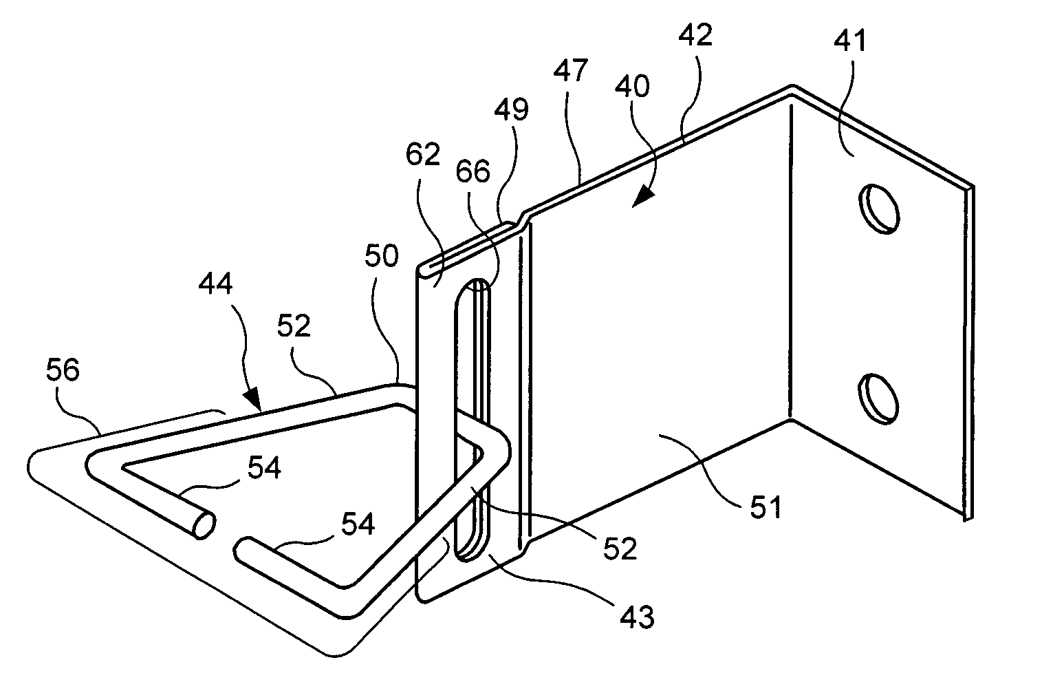
[0064]This anchoring system, discussed in detail hereinbelow, has a high-strength wall anchor with a doubled-walled wing and a veneer tie. The base of the wall anchor is surface mounted on an insulated dry wall structure. In the first embodiment, the inner wythe of the cavity wall has an exterior panel-type insulation vertically disposed thereon. As the veneer being anchored is a brick veneer, the anchoring system includes sufficient vertical adjustment so as to avoid any misalignment.

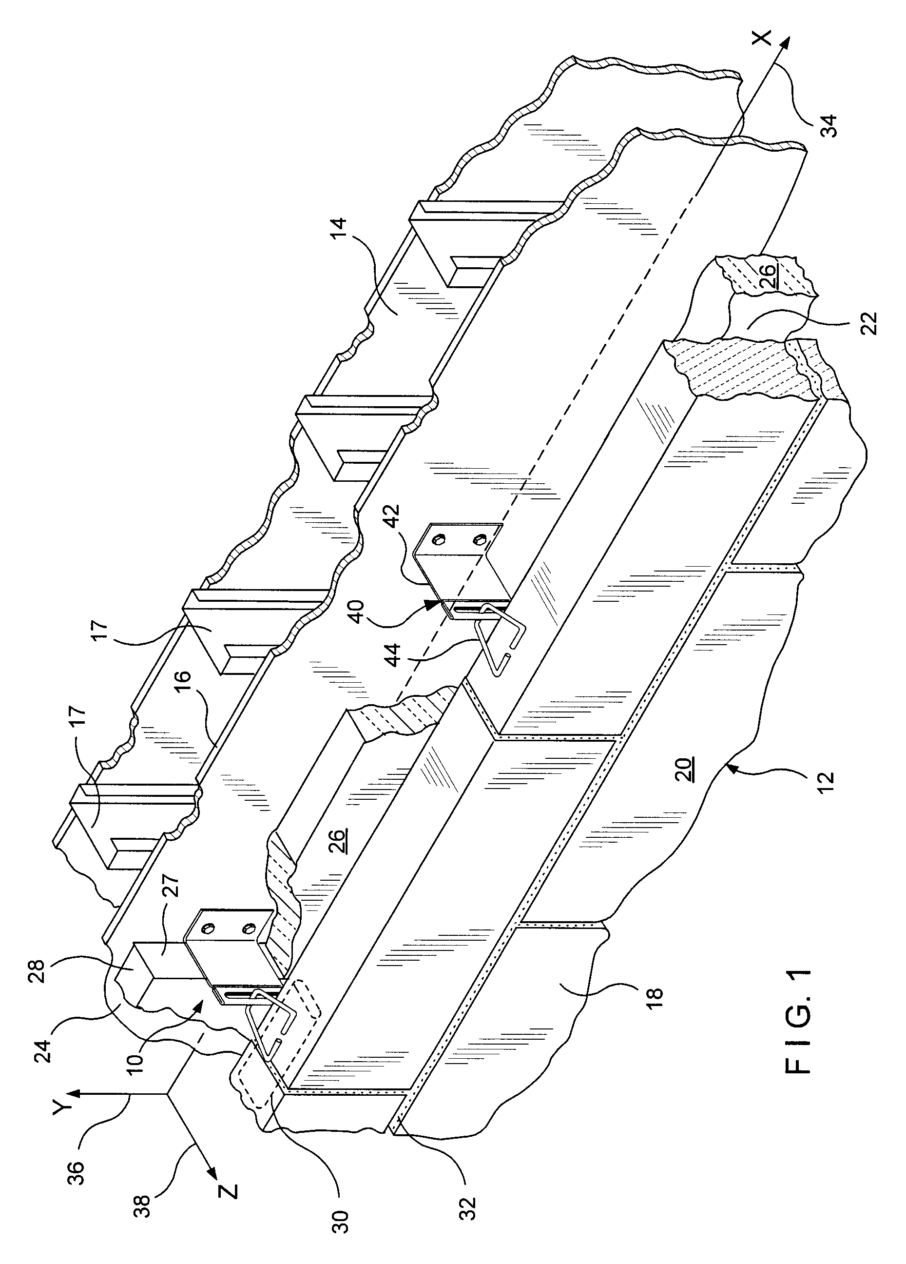
[0065]Referring now to FIGS. 1 through 4, the first embodiment shows a surface-mounted anchoring system suitable for cavity wall constructs under high-wind load conditions. The high-wind load anchoring system for cavity walls is referred to generally by the numeral 10. A cavity wall structure 12 is shown having an inner wythe or dry wall backup 14 formed from sheetrock or wallboard 16 mounted on metal studs or columns 17. The cavity wall 12 also includes an outer wythe or facing 18 of brick 20 construc...

second embodiment

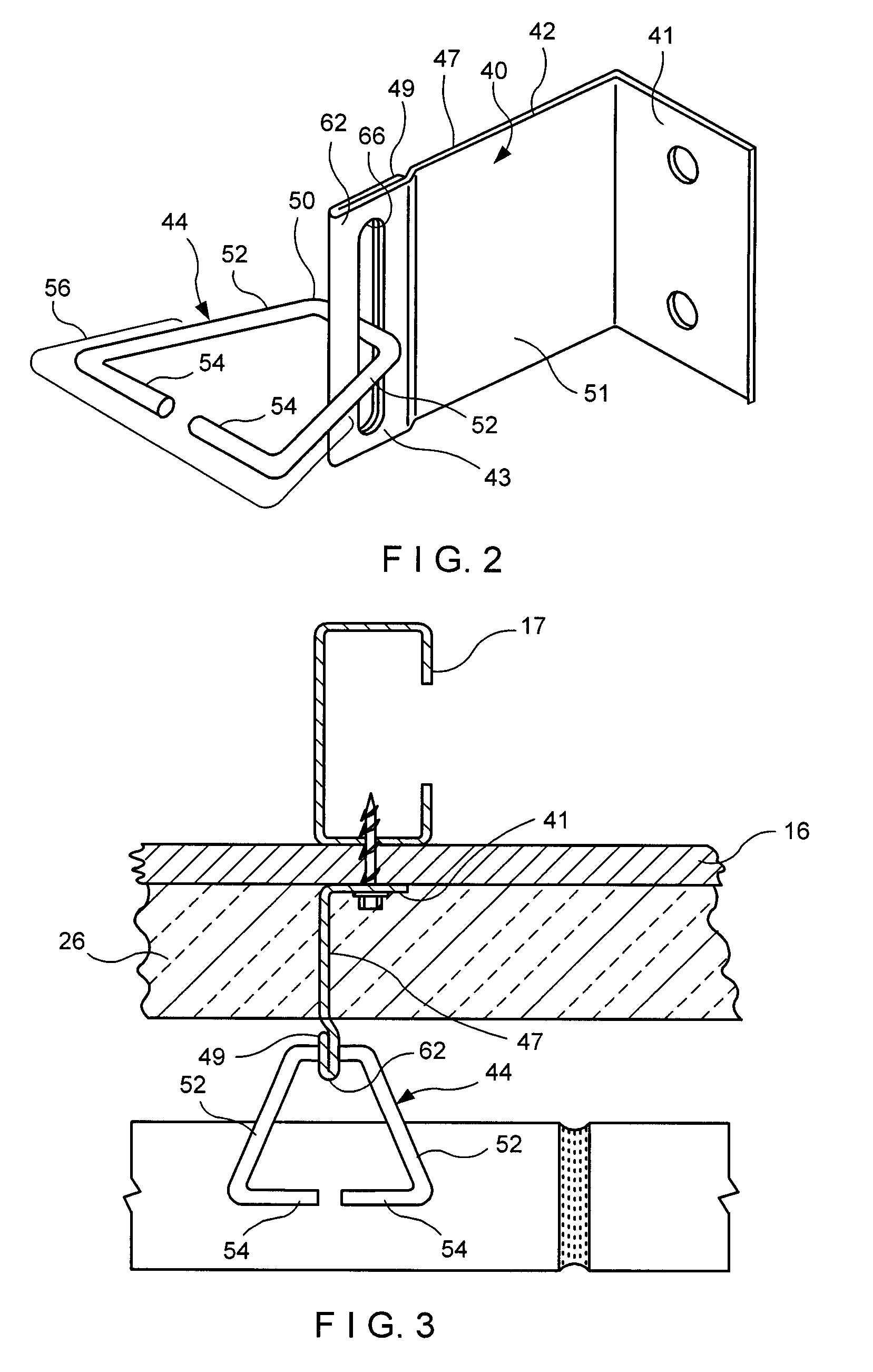
[0080]The wall anchor construct of the second embodiment is seen in more detail in FIGS. 6 and 7. Two double-walled wings 143, vertically disposed, extend horizontally from and coextensively with the base 141 of the wall anchor 140. Each double-walled wing 143 is contoured with a vertically elongated aperture 166 which interengages with the rear leg 150 of the veneer tie 144 that is threaded therethrough. The aperture 166 is constructed to be within predetermined dimensions to restrict movement along the z-axis. The dimensional relationship between the aperture 166 and the veneer tie 144 permits range of movement of the veneer tie 144 along the y-axis 136 while limiting z-axis 138 movement. As a result of this structural arrangement, the veneer tie 144 remains horizontally disposed within the x-z plane of bed joint 130 so that external compressive forces bearing against the face of the outer wythe 118 are transmitted along the veneer tie body 144 and not broken into components.

[0081...

third embodiment

[0088]In the third embodiment, the improvement is the enhanced strength and performance of the double-walled wing structure 243 which absorbs the burden of high-wind forces to resist deformation of the wall anchor 240 coupled with the snap-in wire 265 structure which provides reinforcement against seismic forces, thereby providing improved connection security and motion stability to the high-wind load anchoring system 210 of this invention. Maximum pull resistance is achieved when the juncture of the double wall 249 is formed to align with the central plane 247 of the single planar wall 251.


PUM


Abstract

High-wind load wall anchors and high-wind load wall anchoring systems for cavity walls are described which utilize double-walled anchor constructs with interengaging wire formative veneer ties. The high wind load anchors are mounted upon an interior cavity wall and the veneer ties are embedded within joints of an exterior cavity wall. The anchors have an aperture, for threading the veneer ties therethrough and restricting undesired movement, coupled with a double-walled wing structure to resist anchor deformation by high-wind forces. For resistance against seismic forces, the high-wind load wall anchoring system has a reinforcement wire which snaps into contoured veneer ties.

Description

BACKGROUND OF THE INVENTION[0001]1. Field of the Invention[0002]This invention relates to wall anchors and anchoring systems for cavity walls. More particularly, the invention relates to systems for cavity walls subjected to high-wind loading conditions.[0003]2. Description of the Prior Art[0004]Emergent conditions foster innovation. Dangerous conditions persist—tragedy strikes—change occurs. Whether it is a traffic light at a busy intersection or a less than substantial seawall facing a hurricane, society seems naturally to procrastinate.[0005]Hurricane Katrina formed Aug. 23, 2005 and reached peak strength on Aug. 28, 2005 with one-minute sustained winds of 175 mph. In December 2005, the Federal Emergency Management Agency (FEMA) issued an analysis of Attachment of Brick Veneer in High-Wind Regions. Even with such a remarkable background, the anchoring of brick veneer to a variety of backup walls faces a dearth of standards.[0006]The FEMA analysis of brick veneer failures modes ar...

Claims


Application Information

Patent Timeline
Patent Type & Authority Patents(United States)
IPC IPC(8): E04B1/16
CPCE04B1/4178
Inventor HOHMANN, JR., RONALD P.
Owner HOHMANN & BARNARD INC
Why Eureka
Try Eureka