Method and apparatus for introducing an intravenous catheter

a technology of intravenous catheter and catheter inserting device, which is applied in the direction of intravenous devices, medical syringes, intravenous syringes, etc., can solve the problems of difficult piercing, difficult to pierce, and difficulty in introducing the cannula

Active Publication Date: 2012-06-19
WEXLER TOBY J
View PDF13 Cites 49 Cited by
  • Summary
  • Abstract
  • Description
  • Claims
  • Application Information

AI Technical Summary

Benefits of technology

[0012]The stem portion further includes a knob for withdrawing the plunger, thereby retracting the plunger and its attached needle a short distance from within the cannula. Retraction of the plunger forms a vacuum in the annulus between the needle and cannula, thereby drawing blood from a blood vessel or fluid from an anatomical space into the cavity created by displacement of the plunger within the tubular member, thereby indicating a proper placement of the cannula within the blood vessel or space. If no blood is retracted into the tubular member, the plunger is compressed and the entire assembly may then be extended or repositioned and the plunger can again be retracted until blood becomes visible within the tubular member. When blood is visible within the plunger chamber, the cannula can then be deployed, thus moving the cannula farther into the lumen of the blood vessel. The plunger and needle can then be withdrawn from within the transparent tubular member. It is also envisioned that the tubular member, may be fitted with a self healing barrier for passing medication via a syringe needle or be provided with a twist type coupling for attaching a hose or the like for continuous medications.

Problems solved by technology

Several factors complicate the successful placement of I.V. catheters.
For example, the inherent instability of blood vessels often makes them very difficult to pierce.
Furthermore, the needle or Trocar may miss the blood vessel completely, pass through the blood vessel, or the needle or Trocar may enter the blood vessel but the cannula fails to make penetration when the practitioner attempts to deploy the cannula.
Frequently, poor cannula placement causes the cannula to be expelled or displaced from the blood vessel by movement of the cannula hub while anchoring the cannula assemble to the patient, or attempting to use the cannula to administer fluid therapy.
However, this is not an indication that the blood vessel has been penetrated properly or that the cannula tip has fully penetrated the lumen of the blood vessel.
It then becomes very difficult to reacquire the blood vessel because a clot often forms in and around the blood vessel, which prohibits further flashback into the flashback chamber already filled with blood.
Unfortunately, as has been explained, blood withdrawn through the needle only serves to verify that the needle is within the blood vessel.
Threading the cannula within the lumen of the blood vessel is the current challenge.
If the cannula is not well within the lumen of the vessel it will deflect off the vessel wall and blow the vein.
Difficulty placing the cannula has also resulted in the use of butterfly catheters which do not use a cannula, but instead leave only a sharp needle within the vessel.
Unfortunately, except in very short term use, these will cause trauma to the vein if any movement occurs at the puncture site.
When the cannula is subsequently deployed, subcutaneous hemorrhage occurs resulting in a large swelling at the site of the venipuncture.
This problem frequently occurs when the practitioner is trying to find a vein and actually has the needle in the vein but does not know it due to failure to get a positive flashback in the catheter flash back chamber.
This is a very frequent malfunction of the current catheter assemblies because they rely on blood pressure to give flashback.
However, blood pressure can be weak due to many common conditions, such as small veins, dehydration, sclerosis of the vein from prior venipuncture, or medical conditions.

Method used


Image

  • Method and apparatus for introducing an intravenous catheter
  • Method and apparatus for introducing an intravenous catheter
  • Method and apparatus for introducing an intravenous catheter

Examples


Embodiment Construction

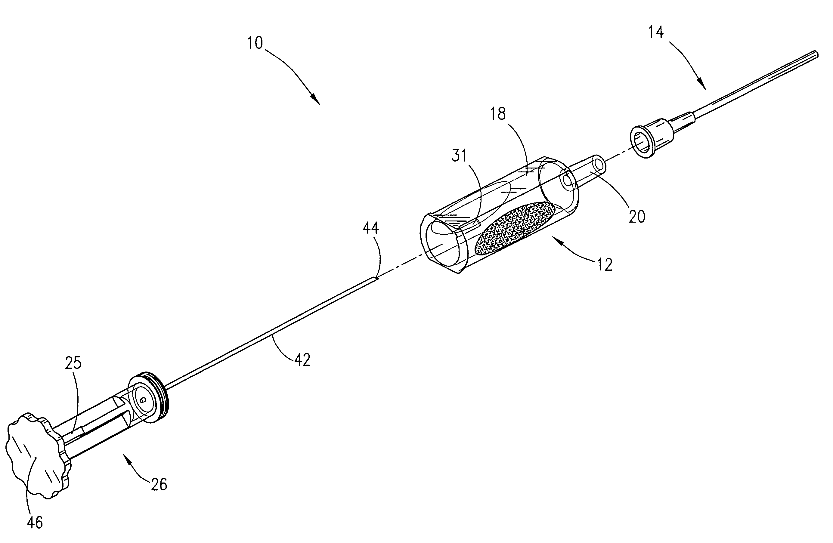
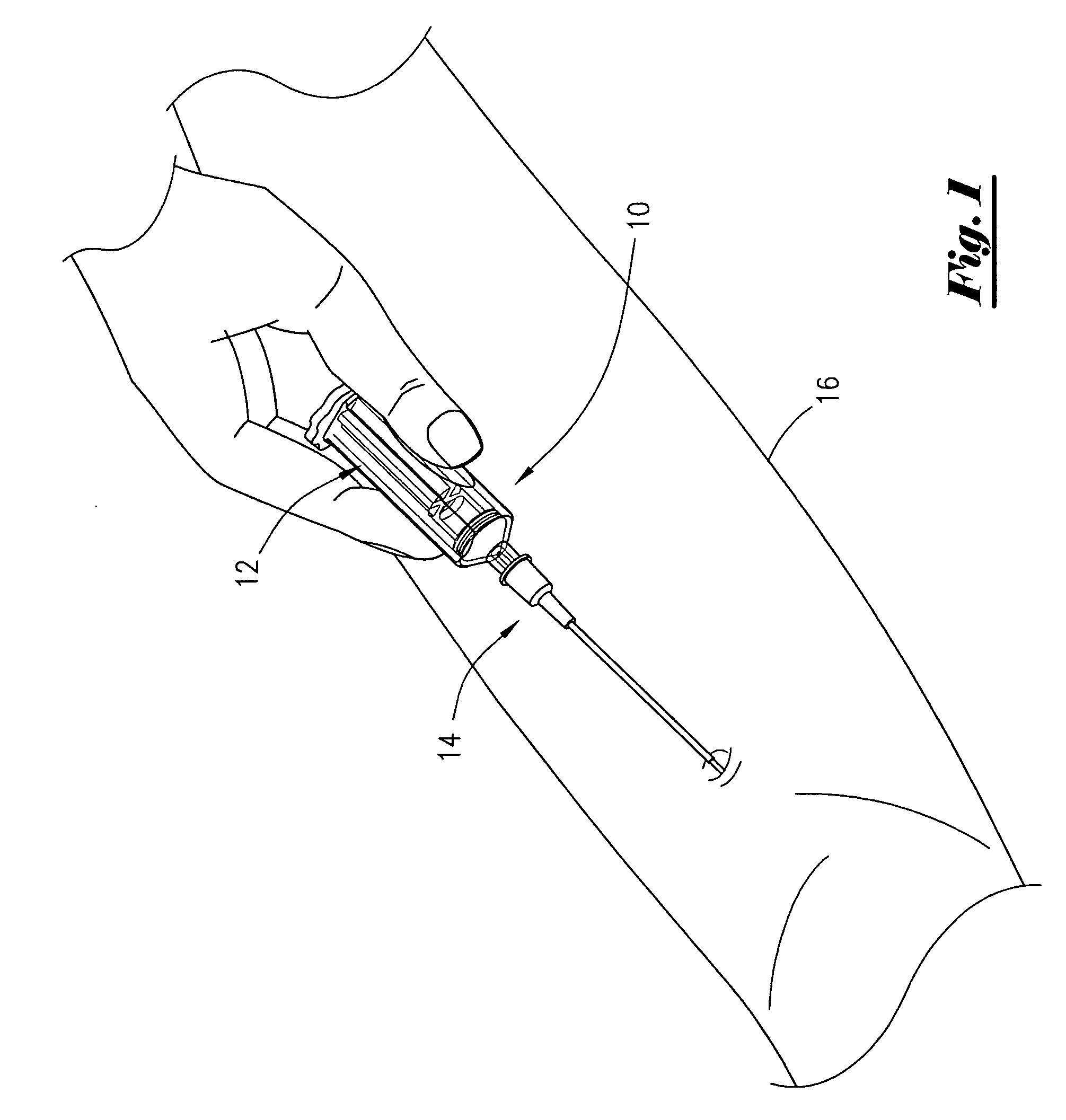
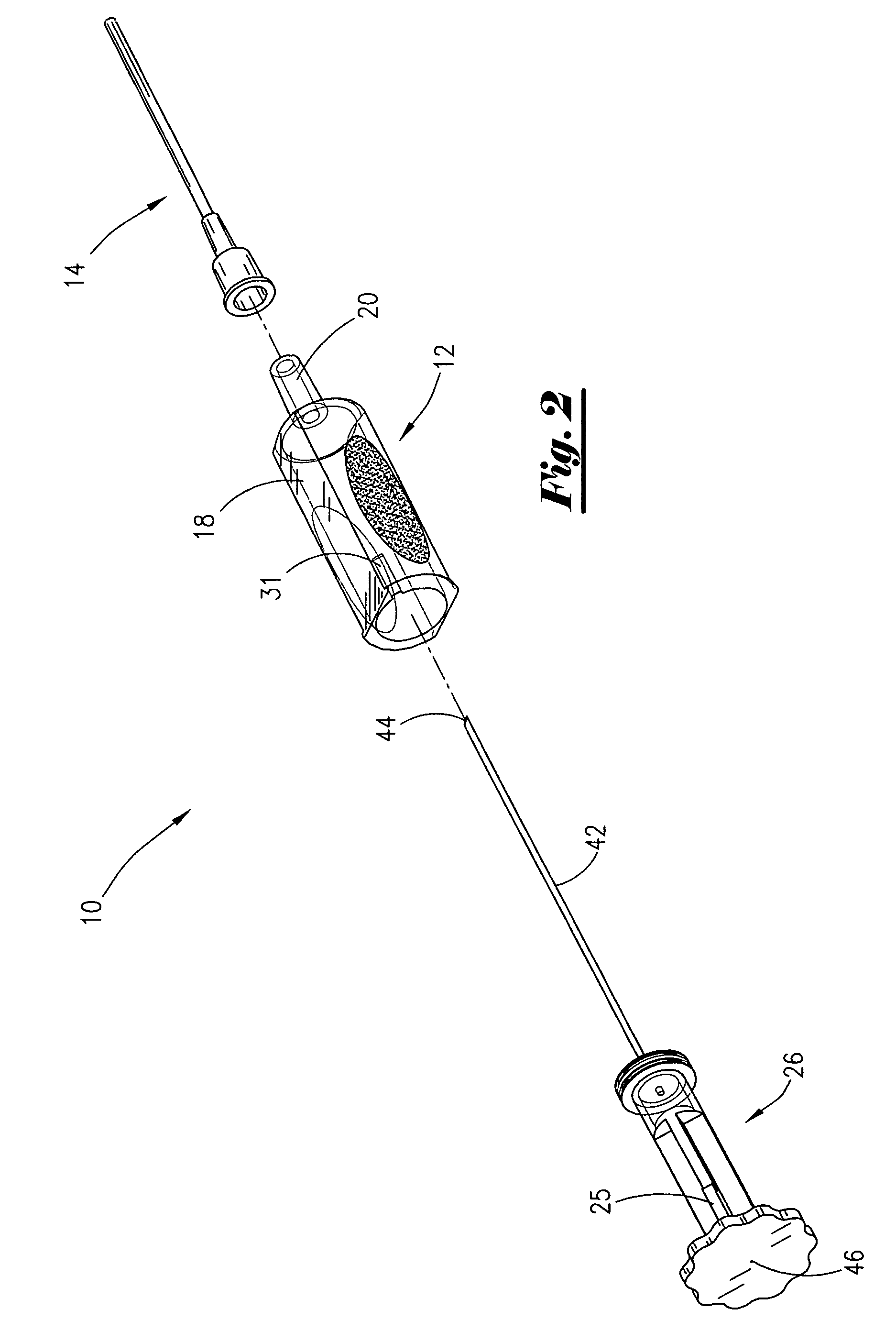
[0026]As shown in FIG. 1, a practitioner is using a new catheter insertion apparatus 10 to insert the catheter assembly 14 into a patient's arm 16. The insertion assembly 12, in addition to the catheter assembly 14, includes a transparent sleeve 18 and plunger assembly 26 as shown in FIG. 2. As further seen in FIG. 3, the transparent sleeve 18 is a transparent elongated tubular member open at each end with a nipple portion 20 at one end. The nipple portion 20 is tapered to fit within the hub member 54 of the catheter assembly 14 to which the cannula 52 is attached, therefore practically any catheter of the proper size and length made for use with a syringe may be used with the new insertion assembly 12.

[0027]As further seen in FIG. 3 and FIG. 4, the exterior of the transparent tubular transparent sleeve 18 includes flat areas 22 on both upper and lower sides as well as concaved shaped sides 24 provided with embossing to assist in gripping the transparent sleeve 18 using only the pra...


PUM


Abstract

A catheter insertion apparatus with visual indication of needle penetration of a blood vessel and placement of the catheter cannula within the blood vessel, using blood vessel pressure to indicate needle penetration by the presence of blood within a transparent chamber within the apparatus and the displacement of a plunger to create a negative pressure on the cannula and thus allowing blood to be visible within the catheter hub thereby indicating the introduction of the cannula into the blood vessel.

Description

1. FIELD OF THE INVENTION[0001]The present invention relates generally to methods and apparatus for introducing a peripheral Intravenous (I.V.) catheter into a subcutaneous blood vessel, and more particularly to an apparatus and method for inserting a cannula into a blood vessel using an insertion apparatus having suction capability for providing a visual indication of the positive placement of the cannula within a blood vessel.2. GENERAL BACKGROUND[0002]It is a well known, and the established practice, for inserting a catheter into subcutaneous blood vessels, to use a cannula and needle assembly for starting an I.V., thereby establishing a continuous medication injection site or venipuncture site to withdraw blood from the blood vessel. Such procedures commonly use an over the cannula needle process whereby a hollow bore needle resides within the cannula hub and which also extends slightly beyond the end of the flexible cannula. The cannula may also be introduced by way of a solid ...

Claims


Application Information

Patent Timeline
Patent Type & Authority Patents(United States)
IPC IPC(8): A61M5/178
CPCA61M25/0693A61M25/0606
Inventor WEXLER, TOBY J.
Owner WEXLER TOBY J
Why Eureka
Try Eureka