
Image sensing device

a sensing device and image technology, applied in the field of image sensing devices, can solve the problems of signal saturation, defective pixel always becomes a black dot, and the detected signal is saturated, and achieve the effect of correct detection of defective pixel

Inactive Publication Date: 2012-06-19
PIONEER CORP +3
View PDF3 Cites 7 Cited by
  • Summary
  • Abstract
  • Description
  • Claims
  • Application Information

AI Technical Summary

Benefits of technology

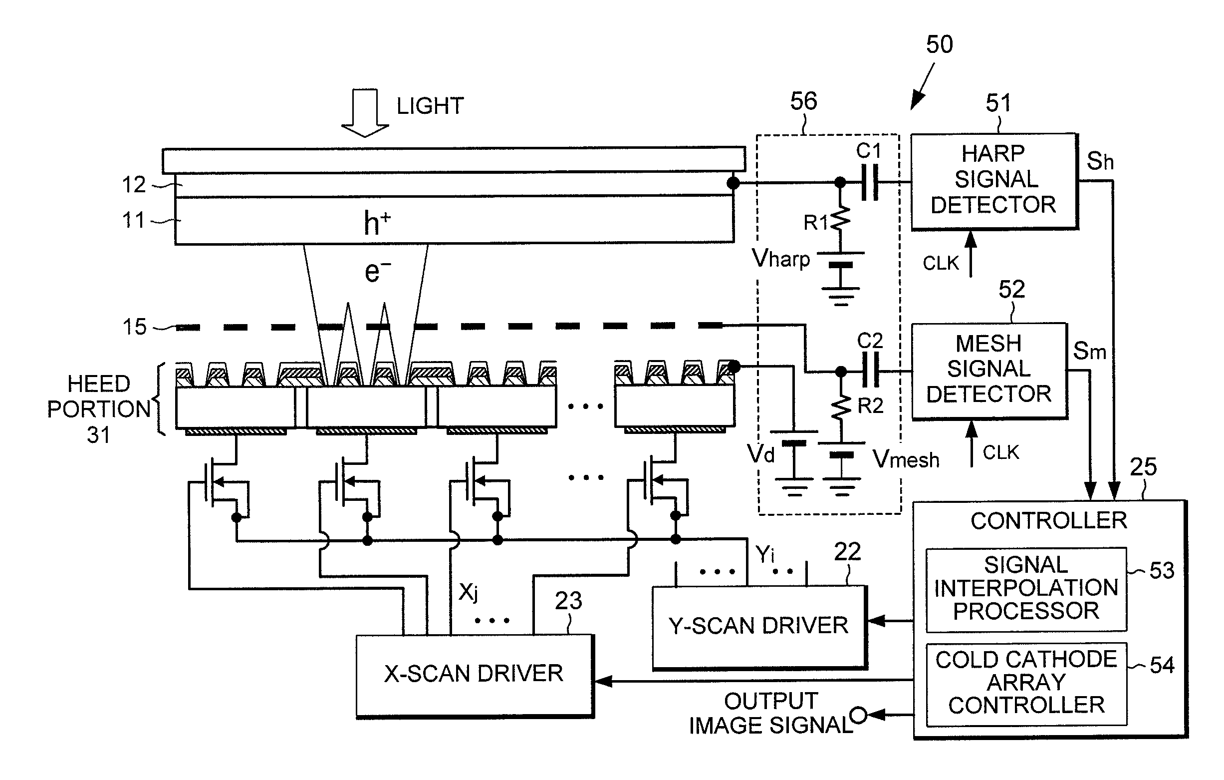
The present invention provides an image sensing device that can detect defective pixels, such as irregular electron emission pixels or residue charge pixels, and accurately perform electron emission control and sensed image data interpolation processing based on the detected pixel information. The device includes an electron emission source array, a photoelectric conversion film, and an intermediate electrode, and outputs an image signal through the combination of holes in the photoelectric conversion film and part of electrons emitted from the electron emission source array. An intermediate electrode current detector applies a positive potential to the intermediate electrode and detects a current flowing in the intermediate electrode, which is synchronized with a clock signal for dot sequential scanning of each electron emission source. The device also includes a residue hole identifier that identifies an electron emission source that emits a smaller amount of electrons than the amount of holes generated in the photoelectric conversion film based on both the current flowing in the intermediate electrode and the current flowing in the photoelectric conversion film.

Problems solved by technology

However, if a very bright image is incident on the photoelectric conversion film, an excessively large amount of hole charge is accumulated in one pixel area of the photoelectric conversion film, and the amount of electrons emitted by the electron emission source is insufficient to neutralize the accumulated holes, causing a problem of detected signal saturation when image information is read.
In addition, due to defective pixels of the cold cathode array, there is a problem, for example in that there is a pixel which cannot detect (or reproduce) an image signal since no or almost no electrons are emitted from the pixel or there is a pixel which causes signal saturation even though the brightness of incident light is normal since the amount of emitted electrons is less than a criterion value or a required value.
Such a defective pixel always becomes a black dot, which is obtrusive noise in terms of image quality.
However, in the related art, a pixel for interpolation is specified from the reproduced image and thus there is a problem in that it is difficult to determine whether the reason why the pixel is black is that the sensed image is black or that the pixel is defective.
In addition, there is a problem in that correction is not performed on a pixel that suddenly becomes defective during use.

Method used


Image

  • Image sensing device
  • Image sensing device
  • Image sensing device

Examples


Embodiment Construction

[0022]The embodiments of the present invention will now be described with reference to the drawings.

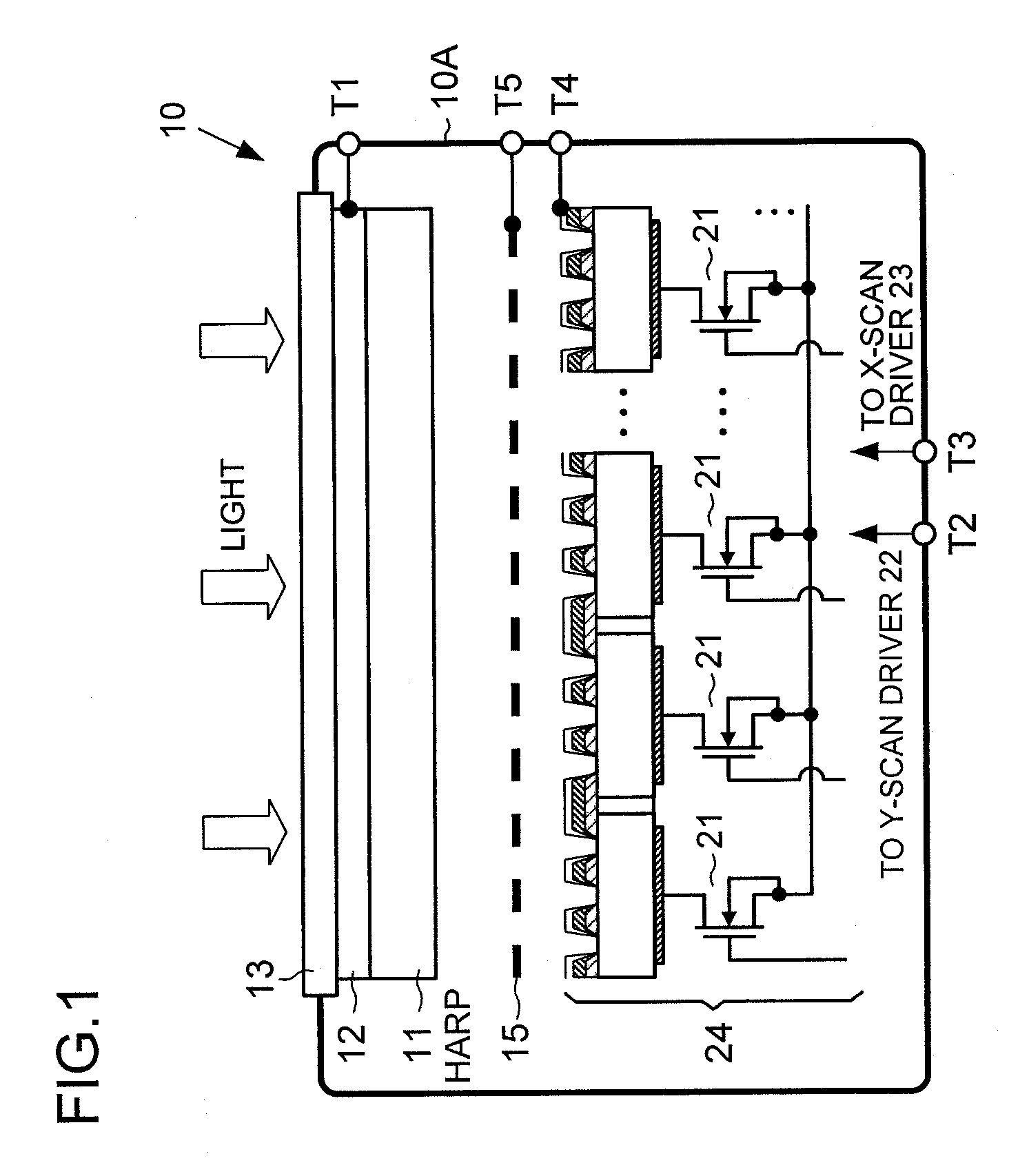
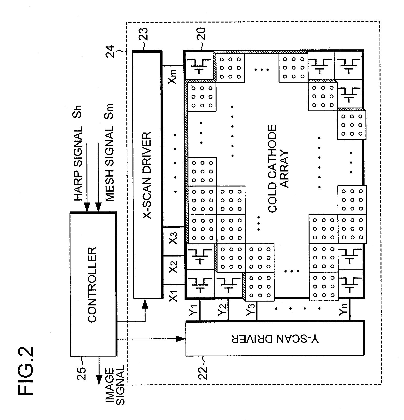
[0023]FIG. 1 is a cross-sectional view schematically illustrating a configuration of an HEED cold cathode HARP image sensor 10. The HEED cold cathode HARP image sensor 10, which will hereinafter also be referred to as a “cold cathode image sensor” for short, is an image sensor which combines a High-efficiency Electron Emission Device (HEED) with a High-gain Avalanche Rushing amorphous Photoconductor (HARP). In more detail, the cold cathode image sensor 10 includes an HARP photoelectric conversion film 11, an HEED cold cathode array chip 24, and a mesh electrode (intermediate electrode) 15 which is disposed between the HARP photoelectric conversion film 11 and the HEED cold cathode array 20. As described later, the HEED cold cathode array chip 24 integrally includes an active-matrix HEED cold cathode array 20, which will hereinafter be referred to as an “HEED cold cathode array” for sh...


PUM


Abstract

A device includes an electron emission source array including a plurality of electron emission sources, a photoelectric conversion film disposed to face the electron emission source array, and an intermediate electrode provided between the electron emission source array and the photoelectric conversion film, and an intermediate electrode current detector that applies a positive potential, relative to a potential of the electron emission source array, to the intermediate electrode and detects a current flowing in the intermediate electrode.

Description

BACKGROUND OF THE INVENTION[0001]1. Field of the Invention[0002]The present invention relates to an image sensing device that includes an image sensor having both an array of electron emission sources and a photoelectric conversion film and a drive circuit that drives the image sensor.[0003]2. Description of the Related Art[0004]An image sensing device, which includes an image sensor having an array of electron emission sources arranged in a matrix, each outputting electrons through application of an electric field, and a photoelectric conversion film, has been proposed. For example, a High-efficiency Electron Emission Device (HEED) has been proposed as an electron emission source (specifically, as a cold cathode electron source) (for example, see Pioneer R&D, Vol. 17, No. 2, 2007, pp. 61-69).[0005]The HEED enables low-voltage driving and features a simple structure, and studies are underway on application of HEEDs to image sensing devices. An example of the photoelectric conversion...

Claims


Application Information

Patent Timeline
Patent Type & Authority Patents(United States)
IPC IPC(8): H01L31/02H04N25/00
CPCH01L27/14609H01L27/14632H04N5/367H04N5/374H01L31/107H04N25/68H04N25/76
Inventor OKUDA, YOSHIYUKINANBA, MASAKAZUEGAMI, NORIFUMIKOBAYASHI, AKIRASUZUKI, HIDEYUKIITOH, SIGEOTANIGUCHI, MASATERU
Owner PIONEER CORP
Learn More