
Development apparatus and image forming apparatus

a technology of development apparatus and image forming apparatus, which is applied in the direction of electrographic process apparatus, instruments, optics, etc., can solve the problems of increasing the amount of added wax, slow conveying speed of developer, and no action to prevent condensation and affixing, so as to prevent the occurrence of developer, simple configuration, and prolong the life of the development apparatus

Active Publication Date: 2012-06-19
SHARP KK
View PDF7 Cites 3 Cited by
  • Summary
  • Abstract
  • Description
  • Claims
  • Application Information

AI Technical Summary

Benefits of technology

The solution reliably prevents toner condensation and affixing without increasing the apparatus size, ensuring longevity and maintaining high-speed processing capabilities while avoiding the need for costly cooling systems.

Problems solved by technology

In a conventional development apparatus, the conveying speed at which developer is conveyed is slow, and there is a comparatively small amount of wax in the toner, so the toner only slightly condenses and affixes to a conveying member that conveys the developer.
Therefore, conventionally nothing has been done to prevent this condensation and affixing.
However, recently, image forming apparatuses have appeared that perform print processing at high speed, and in order to be compatible with these high speed processing devices, wax with a low melting point is used, and there is high tendency for the amount of added wax to be increased.
Also, in the case of a high speed processing device, because circulating conveying of developer in the development apparatus is also fast, when wax with a low melting point is used, and the amount of wax blended is increased, there is the problem that toner is more easily condensed due to heat produced during circulating conveying in the development apparatus.
Also, when temperature is high, there is the problem that toner affixes to a specific portion of the conveying member.
Thus, the problem occurs that the toner deposit becomes still larger, resupplied toner spills out from the toner resupply port 311, and rotation of the first screw conveyor 306 stops.
Such a toner affixing problem can be solved by increasing the size of the image forming apparatus itself, or by using a cooling apparatus, but market demands for reduced size of the image forming apparatus are strong, and providing a cooling apparatus results in increased cost, so addressing the toner affixing problem in these ways is difficult.
Therefore, there is the problem that the apparatus cannot be made compact.
Accordingly, there is a possibility that the coil spring (82) as a whole will be pushed up along the slope of the face of the conveying blade (422), and in this case, there is the problem that the coil spring (82) is restored to the original state before being adequately compressed, a sufficient bursting effect is not obtained, and it may not be possible to reliably break up the toner condensation.

Method used


Image

  • Development apparatus and image forming apparatus
  • Development apparatus and image forming apparatus
  • Development apparatus and image forming apparatus

Examples


embodiment 1

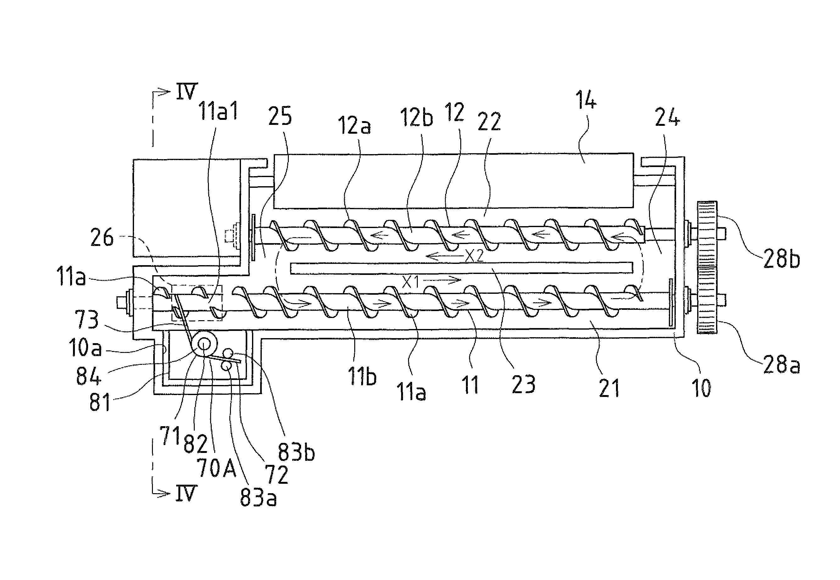
[0081]In Embodiment 1, as shown in FIG. 3, a housing portion 10a that houses the developer affixing prevention member 70 is formed in the case 10 on the left end side of the first screw conveyor 11, and in this housing portion 10a, a support plate 81 is provided in order to support and fix the developer affixing prevention member 70. This support plate 81 is provided extended horizontally from the outside face of the case 10, and on the upper face side thereof, a cylindrical supporting / protruding portion 82 is formed in order to support the developer affixing prevention member 70.

[0082]On the other hand, in Embodiment 1, the developer affixing prevention member 70 is formed with a torsion coil spring 70A formed from the wire rod whose middle is wound in a coil-like shape. As the material that forms the torsion coil spring 70A, it is possible to use, for example, a non-magnetic material such as stainless steel, phosphor bronze, beryllium copper, or aluminum.

[0083]By fitting a winding...

embodiment 2

[0102]Note that in above Embodiment 2, due to the tip end portion 77 side of the plate spring 70B passing by the cut-out portion 11a1, the tip end portion 77 side is instantly restored to its original shape, but the cut-out portion 11a1 is not absolutely necessary. Even when there is no cut-out portion 11a1, due to the tip end portion 77 of the plate spring 70B traveling over the outer circumferential end portion of the fin 11a, instant movement of the tip end portion 77 to the upstream side in the conveying direction X1 is possible. However, in this case, immediately before the tip end portion 77 travels over the outer circumferential end portion of the fin 11a, the side edge 77b of the plate spring 70B and the rotating shaft 11b of the first screw conveyor 11 are temporarily separated, so in consideration of stability of operation, it is preferable that the cut-out portion 11a1 is provided.

[0103]Note that in the above embodiments, a configuration was described in which the develop...


PUM


Abstract

In one embodiment, in a development apparatus in which at least a first screw conveyor has been provided in a case, a developer affixing prevention member that prevents a developer from affixing to the first screw conveyor is disposed in the vicinity of a toner resupply port provided in the case. More specifically, the developer affixing prevention member is formed with a torsion coil spring formed from the wire rod whose middle has been wound in a coil-like shape, and in a state with the wound portion of this torsion coil spring supported by a support plate of the case, one arm portion is fixed to the support plate, and another arm portion is extended so as to contact a fin and a rotating shaft of the first screw conveyor.

Description

CROSS-REFERENCE TO RELATED APPLICATION[0001]This application claims priority under 35 U.S.C. §119(a) on Japanese Patent Application No. 2007-055920 filed in Japan on Mar. 6, 2007, the entire contents of which are herein incorporated by reference.BACKGROUND OF THE TECHNOLOGY[0002]1. Field of the Technology[0003]The present technology relates to development apparatuses used in image forming apparatuses such as copiers, printers, digital multifunction devices, and the like that form images using a developer, and more specifically relates to development apparatuses that use a two-component developer.[0004]2. Related Art[0005]In a conventional electrophotographic image forming apparatus, after uniformly charging a photosensitive body with a charging apparatus, an electrostatic latent image is formed on this photosensitive body with, for example, a laser beam, and this electrostatic latent image is made visible as a toner image by the development apparatus. After the toner image is transf...

Claims


Application Information

Patent Timeline
Patent Type & Authority Patents(United States)
IPC IPC(8): G03G15/08
CPCG03G15/0877G03G15/0893G03G2215/0822G03G2215/0838
Inventor TAKAYAMA, TAKESHI
Owner SHARP KK
Learn More