Cranial fixation device

a technology for fixing devices and cranial bones, which is applied in the field of cranial bones fixation devices, can solve the problems of prolonging the procedure, reducing the safety of cranial bones, and further complicating and prolonging the procedur

Active Publication Date: 2012-06-26
NEUROVENTION
View PDF13 Cites 12 Cited by
  • Summary
  • Abstract
  • Description
  • Claims
  • Application Information

AI Technical Summary

Benefits of technology

[0005]The present invention relates to a cranial fixation device for fixing a bone flap to the skull. The cranial fixation device includes two heads connected by a spring or an elastic cord allowing for placement without the need for instruments to compress the heads or cut off the excess head connectors. The spring provides an even tension allowing for fixation of the bone flap to the skull without excessive pressure.
[0008]Rather than providing a fixed locked position once implanted as described in all the cranial clamps in the prior art, the current invention with the spring or an elastomer band / cord connecting the two heads allow for constrained outward movement of the bone flap relative to the skull in cases of cerebral swelling and subsequently retract the bone flap against the skull once the swelling subsides.

Problems solved by technology

Unfortunately, placement of these cranial clamps as described in the prior art requires additional devices which further complicates and prolongs the procedure.
Their remain several drawbacks to this methodology making the cranial clamps difficult to use and prolong the procedure by requiring an instrument to compress the circular elements together against the bone and once positioned, the need for another instrument for cutting the remaining rod off.
Another drawback includes application of excessive force by squeezing the two clamps together against the skull and bone flap.
Yet another drawback includes the significant effort required to remove the clamps locked in place in cases of re-operation.

Method used


Image

  • Cranial fixation device
  • Cranial fixation device
  • Cranial fixation device

Examples


Embodiment Construction

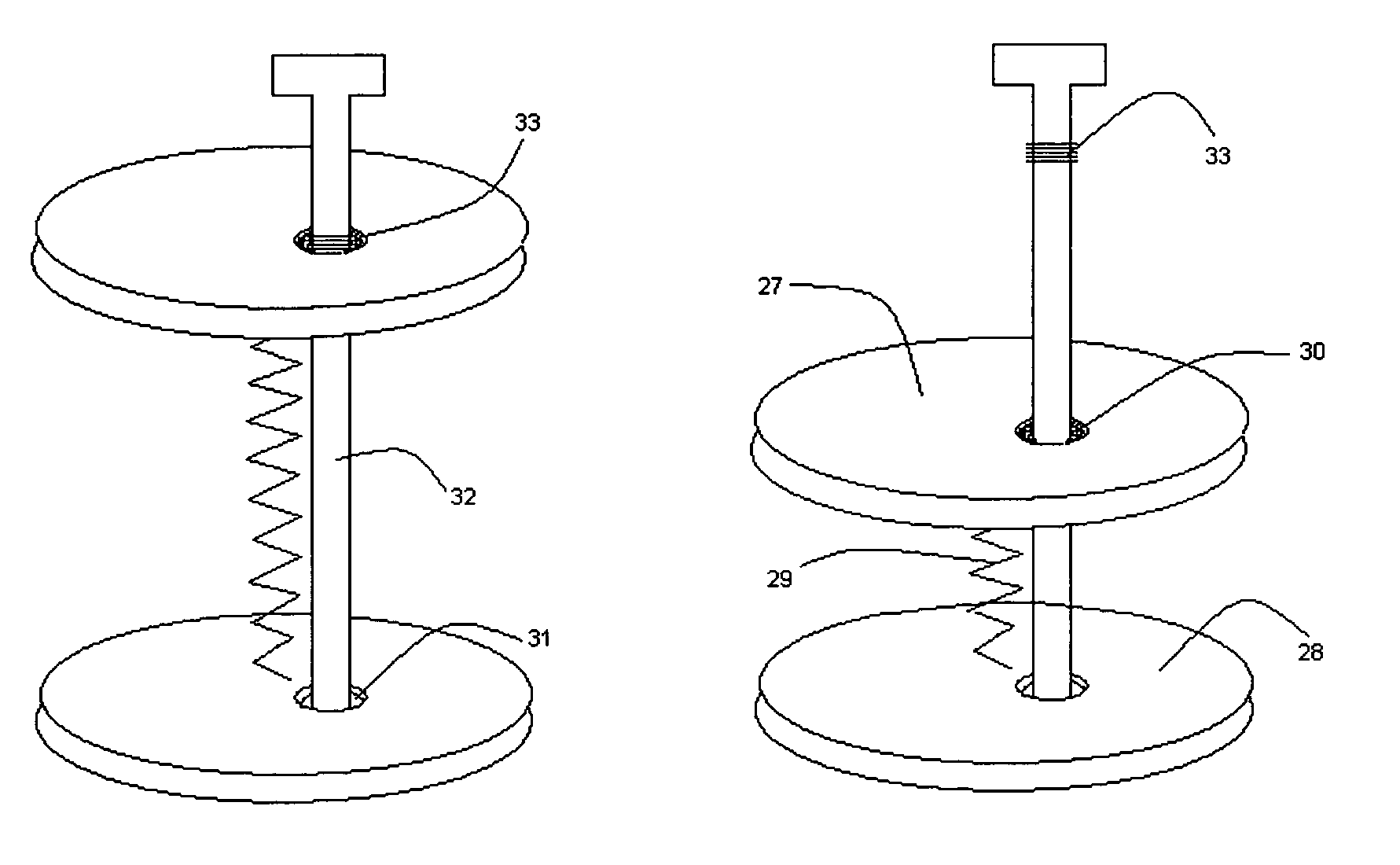
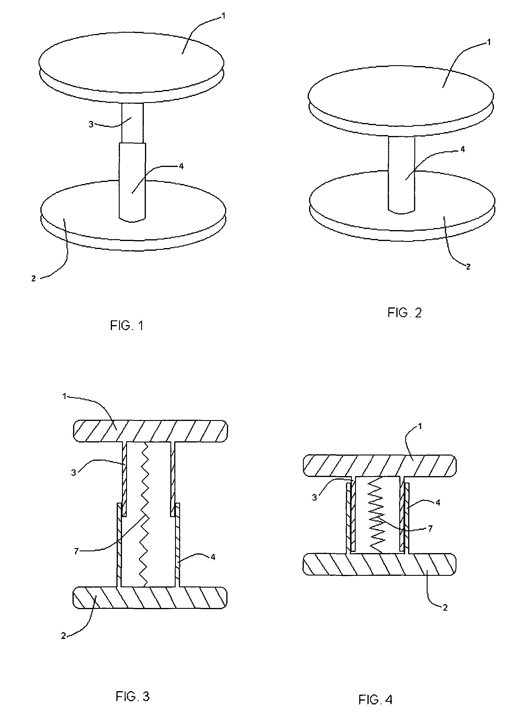
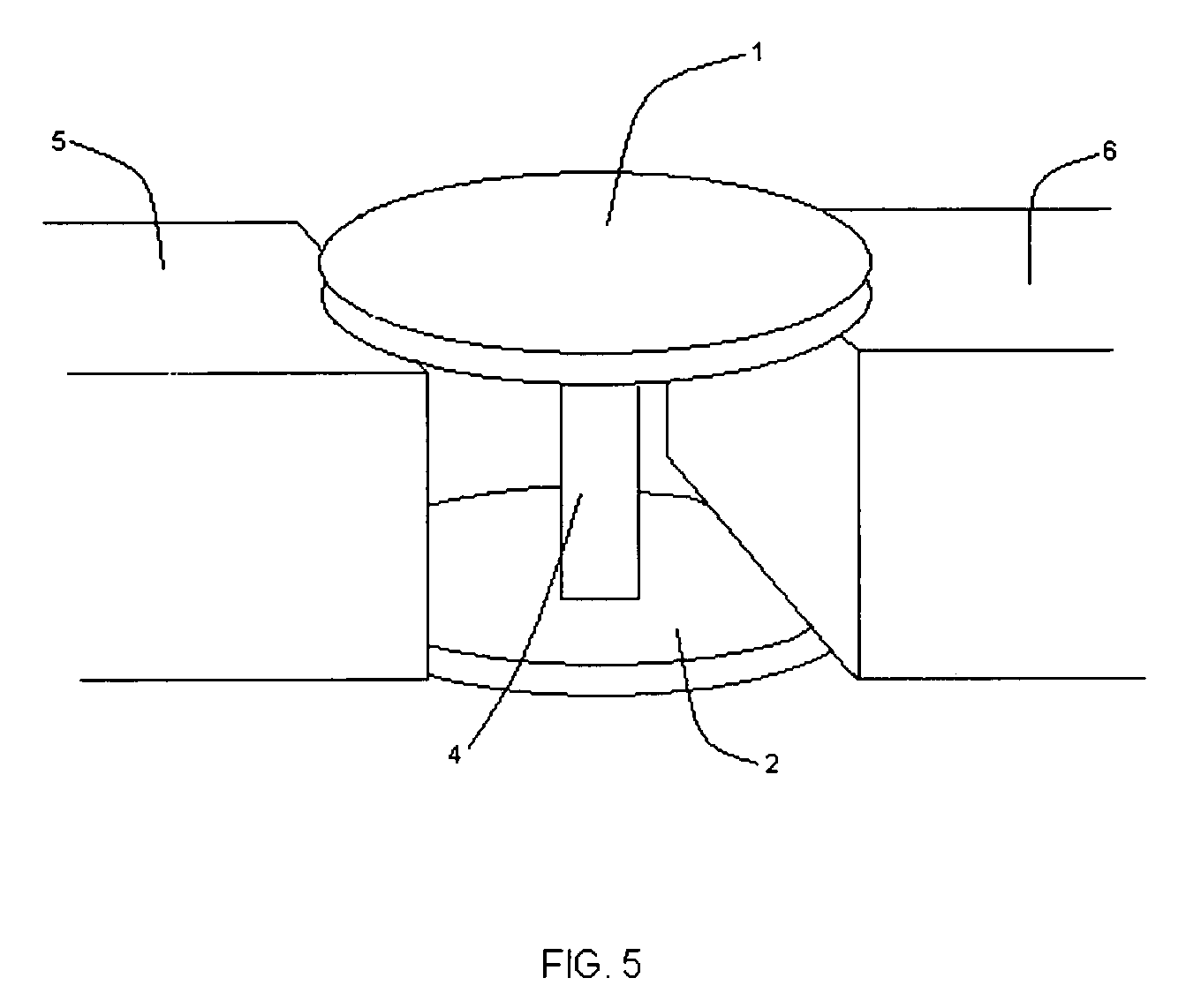
[0075]The present invention provides for an easier and faster cranial fixation as well as easy removal in cases of re-operation. The cranial fixation device as shown in FIGS. 1 and 2 comprise of a head 1 with an extension 3 and a head 2 with an extension 4. The extensions 3 and 4 are telescopic and allow for distraction or compression of the heads relative to each other. FIG. 1 shows the telescopic extensions 3 and 4 in a distracted position and FIG. 2 shows the extensions in a compressed position whereby the extension 3 is contained within the extension 4. FIGS. 3 and 4 illustrate the cross sectional longitudinal view of the cranial fixation device. FIG. 3 shows the two heads 1 and 2 along with their telescopic extensions 3 and 4 in a distracted position. The spring 7 is positioned inside the hollow extensions 3 and 4 and connects the two heads 1 and 2. The spring could also be positioned outside the telescopic connectors, which would also provide for a smaller diameter or width of...


PUM


Abstract

A cranial fixation system and method are provided. The system includes two heads slidably connected with telescopic extensions and a spring or an elastomeric flexible component. The two heads are maintained in a distracted position by a locking mechanism until ready for cranial implantation. Once implanted, the locking mechanism is disengaged, thereby allowing the heads to compress towards each other by the spring and approximate the cranial bone flap to the skull.

Description

BACKGROUND OF THE INVENTION[0001]Neurosurgery routinely involves performing craniotomies for exposure of the brain and intracranial contents for various intracranial pathologies including tumors, head injuries, vascular malformations, aneurysms, infections, hemorrhages, strokes, and brain swelling. A craniotomy involves creation of burr holes and removal of a portion of the skull (bone flap) with subsequent approximation of the bone flap for closure. Several methods and fixation devices are available for re-attaching the bone flap to the skull including small metallic or absorbable plates with screws or wires as demonstrated in U.S. Pat. No. 5,578,036 to Stone et al., U.S. Pat. No. 5,916,200 to Eppley et al, and U.S. Pat. No. 5,916,217 to Manthrop et al. Another method has been the use of cranial clamps consisting of two connected circular elements placed on the inside and outside surfaces of the skull.[0002]Cranial clamps are superior to the plates because they are faster to place ...

Claims


Application Information

Patent Timeline
Patent Type & Authority Patents(United States)
IPC IPC(8): A61B17/04A61F2/08A61B17/84
CPCA61B17/688A61B2017/00991
Inventor KHANNA, ROHIT KUMAR
Owner NEUROVENTION
Why Eureka
Try Eureka