Concentrate burner

a burner and concentration technology, applied in the direction of lighting and heating equipment, blast furnace components, blast furnaces, etc., can solve the problems of the middle part of the shaft, no way of adjusting the amount of turbulence,

Inactive Publication Date: 2012-06-26
OUTOTEC OYJ
View PDF18 Cites 7 Cited by
  • Summary
  • Abstract
  • Description
  • Claims
  • Application Information

AI Technical Summary

Benefits of technology

[0009]extends the processing time of the concentrate mixture particles in the reaction shaft,
[0010]improves the mixing of the substances, which are fed by the concentrate burner, to form a suspension, and the chemical reaction between the same,
[0012]improves the stability of the flame and provides a shape of flame more advantageous than before.
[0019]In an application of the concentrate burner, guide vanes are arranged in the reaction gas chamber to define a swirl angle of the turbulent flow of the reaction gas. As the swirl angle remains constant in various operating conditions, such as alternating turbulence velocities and volume flow rates, the guide vanes can be used to improve the stability of the flame. Therefore, the flow pattern remains quite the same in the varying conditions. The stability of the flame, the mixing, the chemical reaction, and the efficiency of the oxygen use are improved. As a negative radial velocity is achieved, or the radial movement of the process gas is limited, the mixing of the concentrate mixture particles and the process gas can also be improved and, then, the efficiency of oxygen use can be increased. Furthermore, all advantages achievable by the turbulent flow are obtained; in other words, an increase in the processing time of the concentrate mixture particles in the reaction shaft, mixing of the substances that are fed by the concentrate burner to form a suspension, and an improvement in the chemical reaction between the same, an improvement in the efficiency of the oxygen use, and an improvement in the flame stability, and a provision of a flame shape more advantageous than before (a suitable width and a suitable length). The high efficiency of the oxygen use makes the concentrate burner especially advantageous to be used in what are known as the Direct Blister Smelting and the DON process, wherein the degrees of oxidation are high. The Direct Blister Smelting is a flash smelting process of copper, yielding blister copper. The DON process (Direct Outokumpu (Outotec) Nickel Process) is a flash smelting process of nickel.
[0021]In an application of the concentrate burner, there is an area free of guide vanes in the lower part at the lower end adjacent to the discharge orifice. This can facilitate the removal of agglomerations from the vicinity of the guide vanes and, still, it is possible to provide an optimal swirl angle for the reaction gas, determined by the guide vanes. It should be noted that the guide vanes could also be placed closer to the inlet channel, depending on the conditions of the applications.
[0022]In an application of the concentrate burner, the annular discharge orifice of the reaction gas chamber, in the lateral direction and outwards, is limited by a wall part that has the shape of a truncated cone, converging down and inward at an angle θ to the vertical axis. Such an inward inclination of the outer wall of the annular discharge orifice is advantageous, as it can further be used to improve the stability of the flame, increase the processing time of the concentrate mixture particles, improve the mixing and the chemical reaction, and to provide a preferable shape of flame. In most known burner structures, the frusto-conical wall part mentioned above expands down and outwards at an angle to the vertical axis, causing a positive radial velocity in the turbulent flow discharging from the discharge orifice, which in turn can result in a poor mixing of the reaction gas and the concentrate mixture particles, and could thus result in flow conditions disadvantageous to the chemical reaction and the combustion. The positive radial velocity increases with the amount of turbulence increasing. A high turbulence that has a high tangential velocity can have a positive radial velocity so great that the flame may expand (which is not good for the refractory lining of the furnace), and instable burning can occur. Under the effect of the centrifugal forces occurring in the turbulent flow conditions, jointly with the radial positive velocity, some concentrate mixture particles may also reach the wall of the furnace. With an arrangement, where the annular discharge orifice of the reaction gas chamber, in the lateral direction and outwards, is limited by the frusto-conical wall part that converges down and inwards at the angle θ to the vertical axis, a negative radial velocity is provided in the turbulent flow discharging from the discharge orifice. Depending on the angle θ that is inwards inclined, the positive radial velocity can still occur in a very strong turbulent flow that has a very high tangential velocity, but compared to the conventional burner, this positive radial velocity can be considerably decreased. The exact location of the reactions of the discharge area most likely shifts to a place that is more downstream, due to the continuously downward-converging area. With the aid of the angle mentioned above, a preferable flow pattern is provided to stabilize the flame, the chemical reaction is improved, and a preferable shape of flame is provided (not too wide and not too long). This results in a higher efficiency of oxygen use, which, as already mentioned, is critical in the direct blister smelting and, to some extent, also in the DON process.

Problems solved by technology

One problem with the known concentrate burner is that there is no way of adjusting the amount of turbulence.
The turbulence can ignite an excessively effective flame too quickly, causing problems to the middle part of the shaft.

Method used


Image

  • Concentrate burner
  • Concentrate burner
  • Concentrate burner

Examples


Embodiment Construction

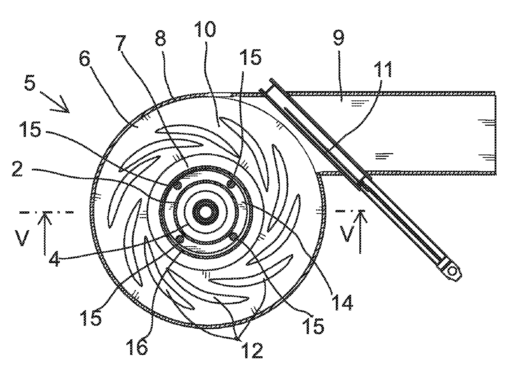
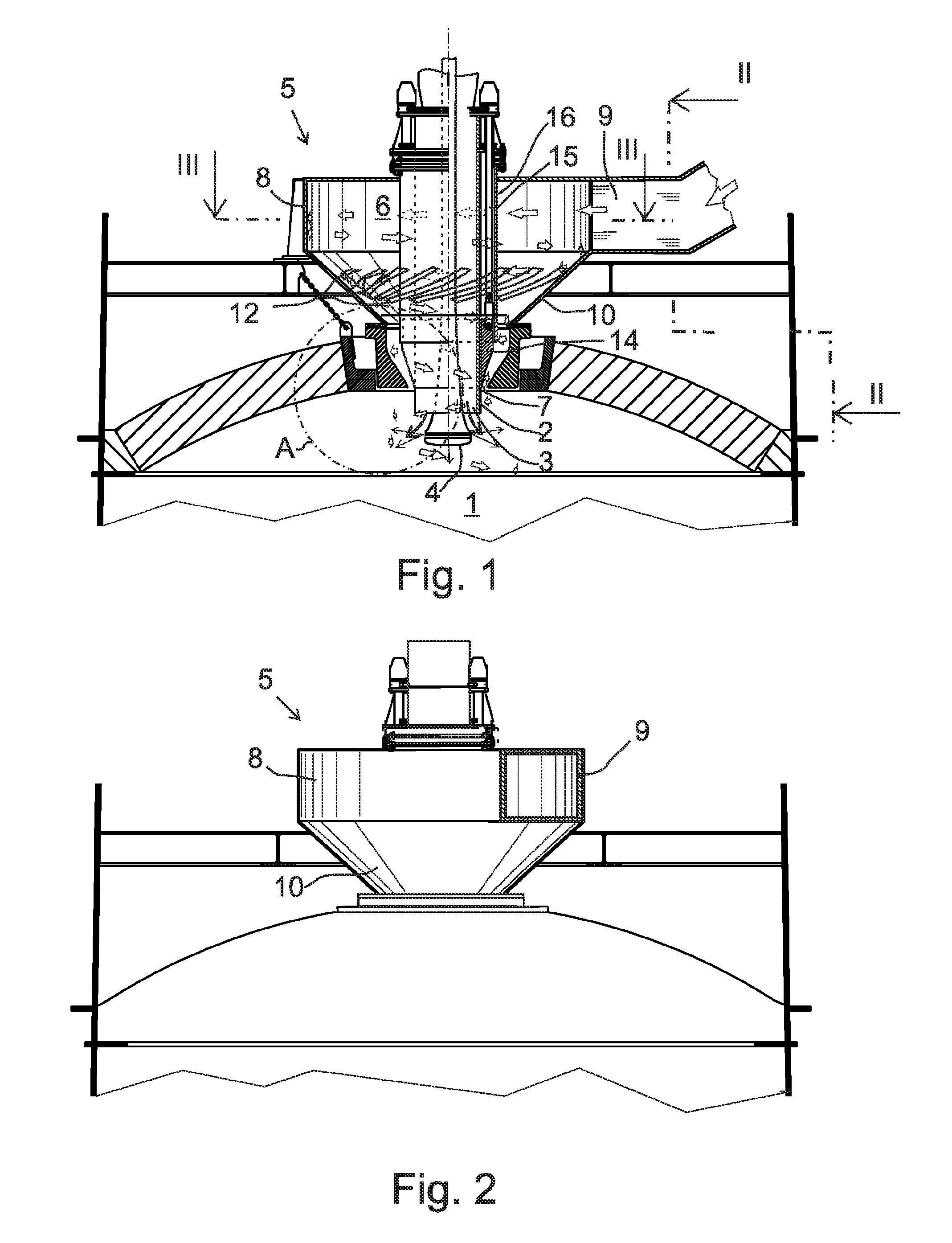
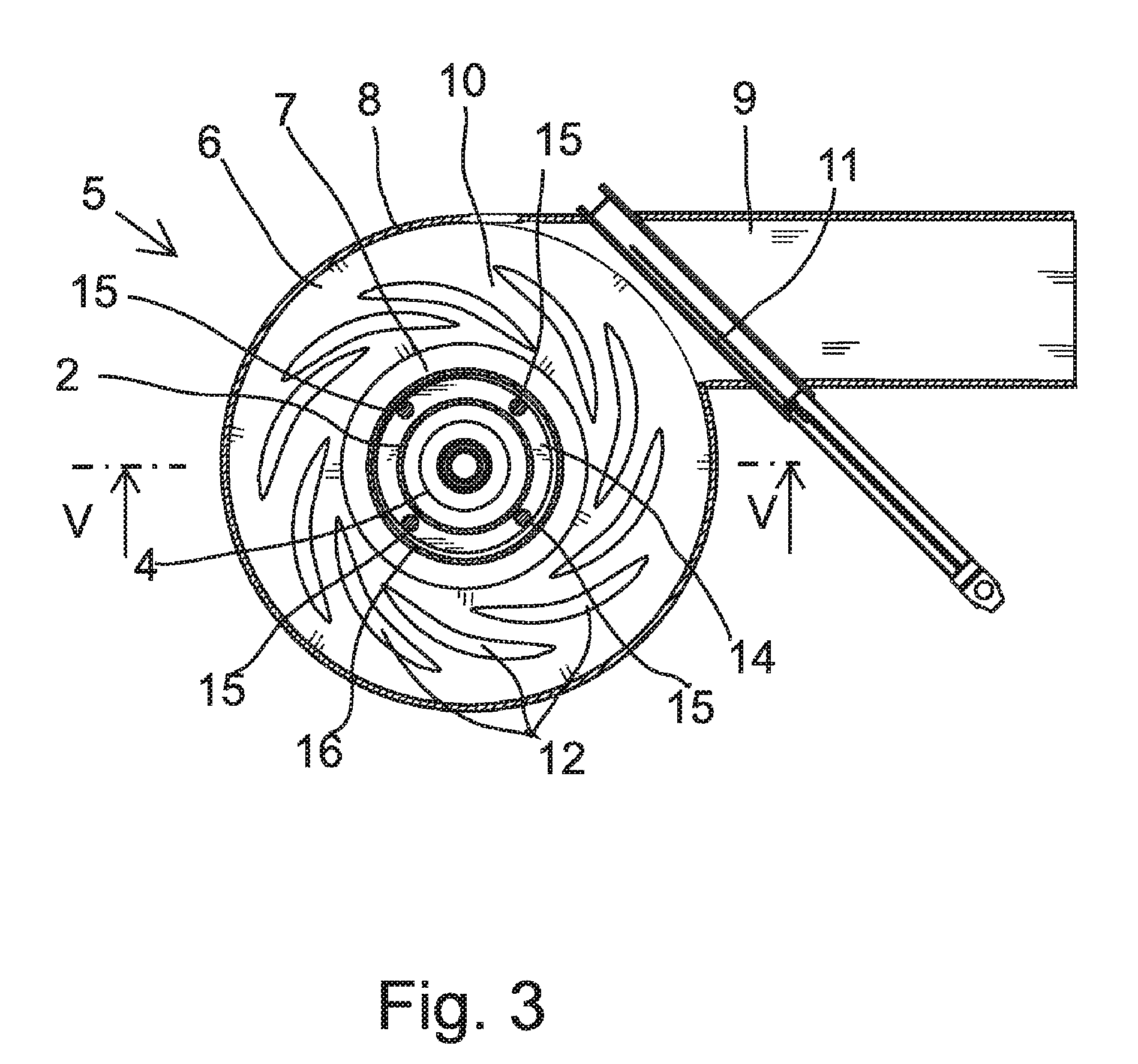
[0030]FIG. 1 shows a concentrate burner that is installed in the upper part of the reaction shaft 1 of a flash smelting furnace to feed pulverous concentrate mixture and reaction gas to the reaction shaft 1 of the flash smelting furnace.

[0031]The concentrate burner includes a feeder pipe 2, its orifice 3 opening to the reaction shaft for feeding the concentrate mixture into the reaction shaft 1. Inside the feeder pipe 2, there is a dispersing device 4 that is placed concentrically, extending to a distance from the orifice 3 towards the inside of the reaction shaft 1. The dispersing device 4 directs the gas that is fed through it from the lower edge of the device to the side towards the flow of solid matter that is directed downwards outside the dispersing device. Furthermore, the concentrate burner includes a gas supply device 5 for feeding the reaction gas into the reaction shaft 1. The gas supply device includes a reaction gas chamber 6, which is located outside the reaction shaft...


PUM

PropertyMeasurementUnit
angleaaaaaaaaaa
angleaaaaaaaaaa
angleaaaaaaaaaa

Abstract

A concentrate burner for feeding a pulverous concentrate mixture and reaction gas into a reaction shaft of a flash smelting furnace. The concentrate burner includes a feeder pipe for feeding a concentrate mixture into the reaction shaft and a dispersing device for directing dispersing gas to the concentrate mixture flowing around the dispersing device. For feeding the reaction gas into the reaction shaft, a gas supply device is provided which includes a reaction gas chamber for mixing the reaction gas with the concentrate mixture, and for directing the concentrate mixture to the side by the dispersing gas. The reaction gas chamber includes a turbulent flow chamber, to which an inlet channel opens tangentially for directing the reaction gas to the reaction gas chamber in a tangential direction. In the inlet channel, an adjusting member is arranged for adjusting the cross-sectional area of the reaction gas flow.

Description

[0001]This application is a national phase entry under 35 U.S.C. §371 of International Application Number PCT / FI2008 / 050478, filed on Sep. 1, 2008, entitled “CONCENTRATE BURNER”, which claims the benefit of Finnish Patent Application Number 20075610, filed on Sep. 5, 2007, all of which are hereby incorporated by reference.FIELD OF THE INVENTION[0002]The invention relates to a concentrate burner defined in the preamble of claim 1.BACKGROUND OF THE INVENTION[0003]A flash smelting process takes place in a flash smelting furnace that consists of three sections: a reaction shaft, a lower furnace, and an uptake. In the flash smelting process, a pulverous concentrate mixture that consists of sulphidic concentrates, fluxes, and other pulverous components, is mixed with a reaction gas by means of the concentrate burner in the upper part of the reaction shaft. The structure of the concentrate burner plays a radical role in the proper functioning of the flash smelting process. The reaction gas...

Claims


Application Information

Patent Timeline
Patent Type & Authority Patents(United States)
IPC IPC(8): F27D3/18
CPCC22B15/0047F27D3/18F27D3/16C22B15/00
Inventor SIPILA, JUSSIPELTONIEMI, KAARLEBJORKLUND, PETERXIA, JILIANG
Owner OUTOTEC OYJ
Why Eureka
Try Eureka