Liquid container with an extraction chimney

a liquid container and extraction chimney technology, applied in laboratory glassware, multi-stage water/sewage treatment, separation processes, etc., can solve the problem of not being able to anticipate the sudden change in the liquid level of the extraction chimney due to the external swashing

Active Publication Date: 2012-06-26
ROCHE DIAGNOSTICS OPERATIONS INC
View PDF9 Cites 24 Cited by
  • Summary
  • Abstract
  • Description
  • Claims
  • Application Information

AI Technical Summary

Benefits of technology

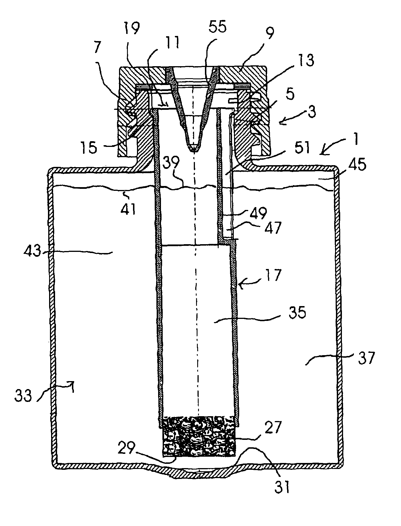
[0010]The flow resistance element serves as a flow brake which ensures that when the liquid container is abruptly braked, onsetting swashing movements of the liquid around the withdrawal chimney are considerably damped and are manifested in a delayed manner as slow changes in the level in the withdrawal chimney. Hence, the flow resistance element forms a “low pass” for the liquid in the withdrawal chimney with regard to the frequency and severity of the swashing movements and liquid level oscillations. When the liquid container is rapidly positioned in a pipetting station e.g. by means of a carousel or rotor carrying the container, only relatively slow changes in the level occur in the withdrawal chimney irrespective of the swashing movements around the withdrawal chimney triggered by the stopping of the container. Thus, the pipetting tip of such an automated pipetting device can be admitted into the withdrawal chimney immediately after the container has stopped and dip into the liquid to the smallest possible depth in order to then pipette. The immersion depth or the level of the liquid in the withdrawal chimney is usually detected by sensory means e.g. by means of capacitive sensors in the case of automated pipetting stations and the immersion depth is controlled according to the sensor information. This can be carried out in a corresponding manner also when using a liquid container according to the invention. As desired the pipetting tip is only wetted on its outer side by liquid over a short length so that only a small entrainment volume of liquid can collect on the outside of the pipette. Surprising rapid changes in the level of the liquid in the withdrawal chimney due to the external swashing effect are not to be expected during the short pipetting time due to the low-pass effect of the flow resistance element. The level of liquid in the withdrawal chimney thus at most only varies slowly and to a dampened degree so that the automatic pipetting device can pipette reliably from the respective calculated fill level in the withdrawal chimney with a low immersion depth of the pipette tip.
[0011]Furthermore, the flow resistance element can be designed such that it acts as a foam brake which substantially prevents the passage of foam from the inner space of the container into the withdrawal chimney.
[0014]According to another embodiment of the invention the flow resistance element is a fine-pored grating sieve made of metal or plastic. Alternatively or in addition the withdrawal chimney can be provided with a plurality of capillary through-bores at its lower end and the area of the withdrawal chimney that is finely perforated in this manner forms the flow resistance element. With the diverse possibilities of realizing a flow resistance element, care should always be taken that it offers the desired flow braking property and swashing movements of the liquid can only result in comparatively slow and dampened changes in the level in the withdrawal chimney.
[0016]As is known, it is proposed that the upper opening of the container has a spout which projects upwards and in particular a screw cap spout the inner surface of which forms the circumferential boundary surface of the container opening. The upper end of the withdrawal chimney can have a flange section with which it is attached to an upward facing shoulder face of the spout. The withdrawal chimney can thus be held in a stable manner it its fitting position in the container.
[0018]Such a venting path allows a rapid and effective pressure equalization between the interior of the liquid container and the environment and it can be manufactured in a simple manner. In this connection through-holes in the casing of the withdrawal chimney for venting purposes can be omitted. In the case of liquid containers of the prior art such through-holes require a limitation of the maximum liquid level if it is intended to prevent swashing liquid from entering through the through-opening into the upper region of the withdrawal chimney. It should be noted that the aspect of the venting path is also independently of significance and thus it can also be used for withdrawal chimneys which are not equipped with a flow resistance element of the above-mentioned type but rather with for example a gap of the conventional type.

Problems solved by technology

Surprising rapid changes in the level of the liquid in the withdrawal chimney due to the external swashing effect are not to be expected during the short pipetting time due to the low-pass effect of the flow resistance element.

Method used


Image

  • Liquid container with an extraction chimney
  • Liquid container with an extraction chimney

Examples


Embodiment Construction

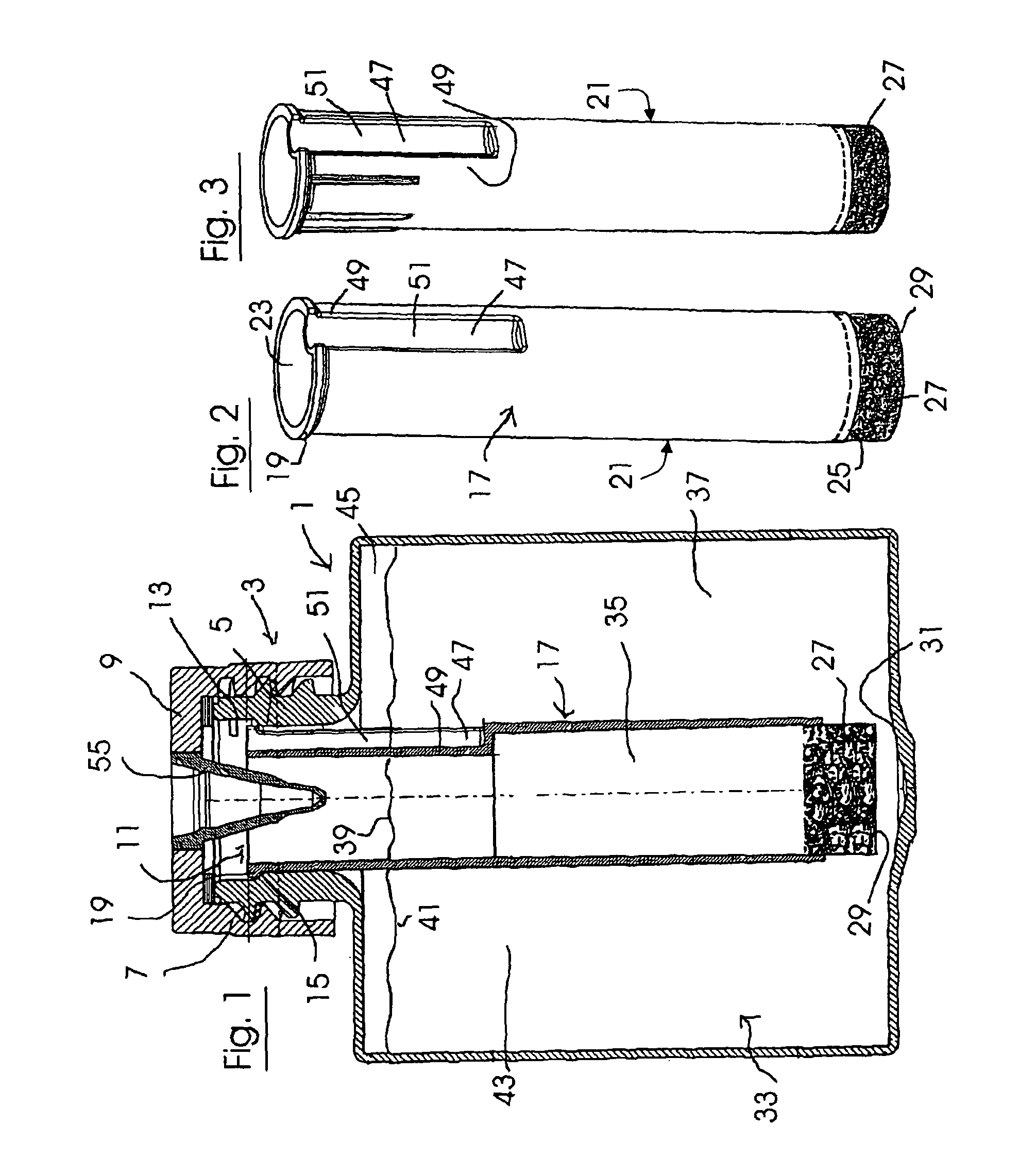
[0023]In FIG. 1 an embodiment example of a liquid container 1 according to the invention is shown in a longitudinal section along a vertical centre plane. The liquid container 1 is a bottle with a screw cap 3. The bottle neck 5 is a screw cap spout with an outer thread 7 which serves as a screw thread for the screw cap 9. The spout-like bottle neck 5 has the withdrawal opening 11 of the liquid container 1 and has a shoulder with a ring shoulder 15 which extends radially inwards on its inner surface / circumferential boundary surface 13 on which a withdrawal chimney 17 with an upper end flange 19 is hung.

[0024]In FIG. 2 the withdrawal chimney 17 is shown separately in a perspective view. In this example it comprises with regard to its basic form a hollow cylindrical tube body 21 which has tube openings 23, 25 on its front ends. The lower tube opening 25 of the tube body 21 is filled out with a finely-porous flow resistance element 27 which is a liquid-permeable plug made of sintered po...


PUM

PropertyMeasurementUnit
cycle timeaaaaaaaaaa
permeableaaaaaaaaaa
outer circumferenceaaaaaaaaaa

Abstract

A liquid container with an upper opening and a tube-shaped withdrawal chimney is disclosed. The withdrawal chimney extends into the container through the upper opening which has a liquid-permeable zone in the form of a finely-porous flow resistance element in its lower end region such that liquid exchange can take place between the withdrawal chimney and the container inner space which surrounds it via the flow resistance element. A venting groove formed by a radial recess of the casing wall of the withdrawal chimney in its upper region may be provided to ensure adequate venting of the space above the liquid level.

Description

CROSS REFERENCE TO RELATED APPLICATIONS[0001]This application is a continuation of International Application No. PCT / EP2007 / 004024 filed May 7, 2007, which claims priority to German Application No. 10 2006 021 404.8, filed May 8, 2006.FIELD OF THE INVENTION[0002]The present invention relates generally to liquid containers for laboratory use, and in particular to a liquid container with an upper opening and a tube-shaped withdrawal chimney which extends into the container and is flush with the upper opening and which has a liquid-permeable zone in its lower end region near to the bottom of the container.BACKGROUND OF THE INVENTION[0003]Liquid containers are used as reagent liquid vessels in automated analyzers. When used in such an automated analyzer, reagent liquid is removed from the liquid containers by automatic pipettors. In modern systems this takes place in a rapid cycle in order to enable a high throughput of respective analytical processes. In this process the liquid contain...

Claims


Application Information

Patent Timeline
Patent Type & Authority Patents(United States)
IPC IPC(8): B01L3/00
CPCB01L3/508B01L3/50825B01L2200/026B01L2300/047B01L2300/048G01N35/10B01L3/00
Inventor SATTLER, STEPHAN
Owner ROCHE DIAGNOSTICS OPERATIONS INC
Why Eureka
Try Eureka