Determining electric grid endpoint phase connectivity

a technology of electric grid and endpoint device, applied in the direction of noise figure or signal-to-noise ratio measurement, flicker reduction in ac network, instruments, etc., can solve the problems of increasing the loss of power and revenue to the utility, keeping up, and meter at the customer endpoint device not guaranteed

Active Publication Date: 2012-06-26
ITRON NETWORKED SOLUTIONS INC
View PDF12 Cites 31 Cited by
  • Summary
  • Abstract
  • Description
  • Claims
  • Application Information

AI Technical Summary

Problems solved by technology

However, when the customer endpoint is physically connected, it may not necessarily be known at that time which phase at the feeder level corresponds to the line at the customer endpoint to which the meter is being connected.
This could be because the utility may have never had that information, or it may not have been kept up to date since physical grid topology is typically modified over time.
Further, if there is a power outage, or if the power is shut down so that a new transformer can be installed, there is no guarantee that the meter at the customer endpoint device will be on the same phase as it was previously.
As the customer density served by a feeder increases, this inaccuracy may increase, and thus, may result in an increased loss of power and revenue to the utility.

Method used


Image

  • Determining electric grid endpoint phase connectivity
  • Determining electric grid endpoint phase connectivity
  • Determining electric grid endpoint phase connectivity

Examples


Embodiment Construction

[0023]For simplicity and illustrative purposes, the principles of the invention are described by referring mainly to exemplary embodiments thereof.

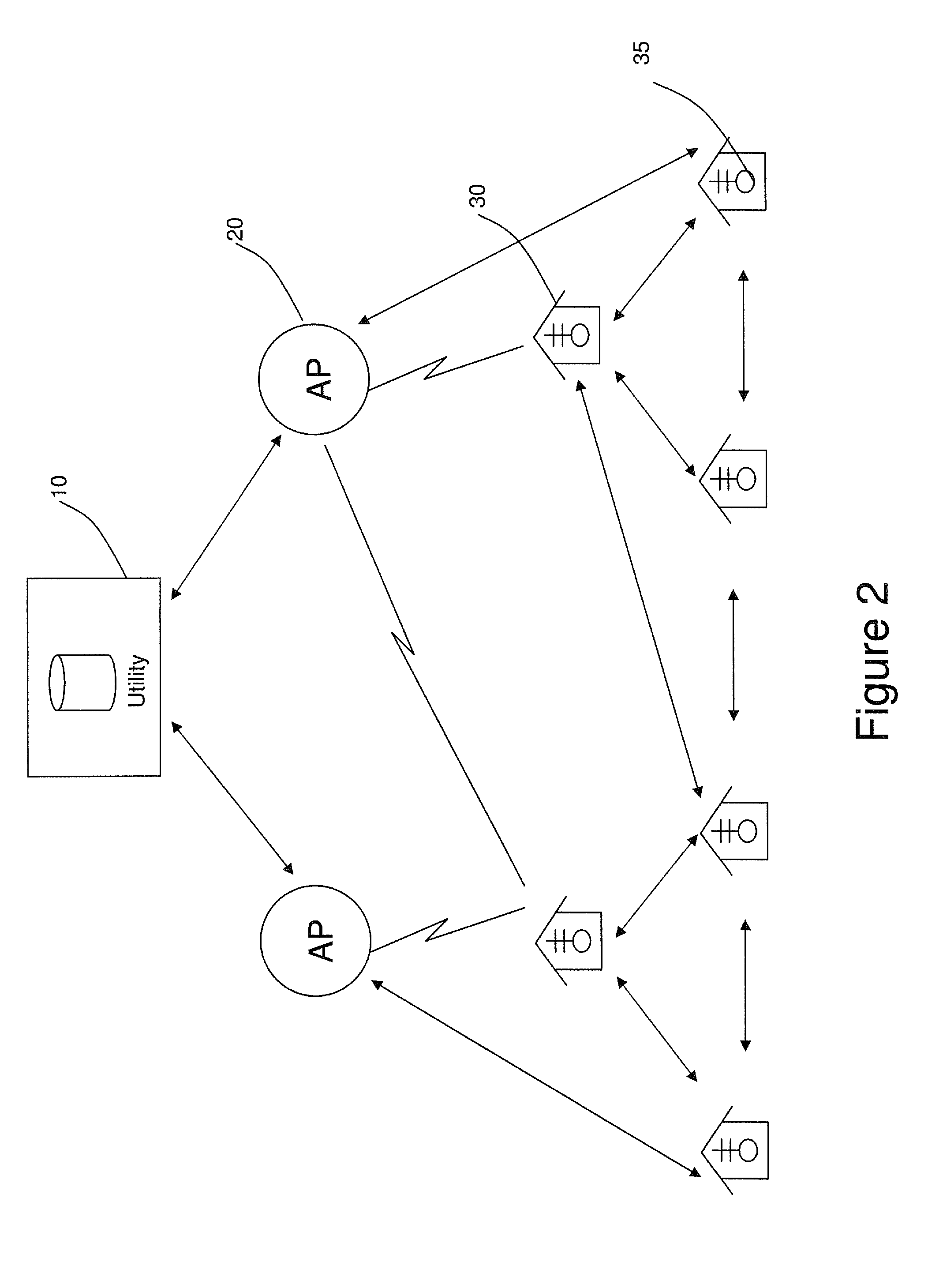
[0024]FIG. 2 is a schematic diagram of a wireless communication network of a power distribution system in which exemplary embodiments may be implemented. The communication network may include a utility back office server 10, a gateway access point (AP) 20, and a plurality of customer endpoint devices 30. The back office server 10 controls communication between the utility and the customer endpoint devices 30 and receives information (e.g., utilization data, power loss reports, and other similar information) from the customer endpoint devices 30. The AP 20 connects to the utility via a WAN (wide area network), the Internet, cellular, or any other network (wired, wireless, optical, etc.), and serves as the direct communication point to the customer endpoint devices 30. The endpoint devices 30 may connect to the AP 20 via a wired, wireless, ...


PUM


Abstract

The service phase of the electrical connection to a customer endpoint device located within a power distribution system is determined by various techniques. At the feeder level, the system may be programmed to induce momentary power interruptions, thereby causing missed zero crossings at the customer endpoint devices. The pattern of these interruptions is a controlled one, designed specifically to avoid causing noticeable disruption even to sensitive devices, but to be unusual enough that it is statistically unlikely to be naturally occurring. The monitoring of the zero crossing information is used to determine the phase of the service line to the customer endpoint devices.

Description

RELATED APPLICATION[0001]This disclosure claims the benefit of prior Provisional Application No. 61 / 094,728 filed on Sep. 5, 2008, which is hereby incorporated by reference in its entirety.FIELD OF THE INVENTION[0002]Exemplary embodiments relate generally to the determination of the service phase of the electrical connection to a customer end-point located within a power distribution system.BACKGROUND OF THE INVENTION[0003]Electric power is generated at a power station and transmitted through a transmission network of high voltage lines. These lines may be hundreds of miles in length, and deliver the power into a common power pool called a “grid.” The grid is connected to load centers (e.g., cities) through a sub-transmission network of normally 33 kV (or sometimes 66 kV) lines.[0004]FIG. 1 is a diagram illustrating a conventional power transmission and distribution system. This diagram is an example of one of variety of known grid topologies and is provided for illustration purpose...

Claims


Application Information

Patent Timeline
Patent Type & Authority Patents(United States)
IPC IPC(8): G01R19/00
CPCG01R29/18H02J13/0048H02J3/00Y02E60/783H02J2003/002Y04S40/123H02J3/002H02J13/0001H02J13/00034Y04S40/121Y04S10/52Y02E60/00H02J13/00009
Inventor VASWANI, RAJVAN GREUNEN, JANAGOSTRER, ALEXANDER
Owner ITRON NETWORKED SOLUTIONS INC
Why Eureka
Try Eureka