Audio transmission system and communication conference device

a technology of communication conference and transmission system, which is applied in the field of audio transmission system, can solve the problems of inability to transmit accurate audio data, difficulty in identifying who spoke on the reception side, and inability to realize sound field with a high level of presence (for example, a feeling of depth) and achieves a high level of presence and simple configuration

Active Publication Date: 2012-06-26
YAMAHA CORP
View PDF11 Cites 35 Cited by
  • Summary
  • Abstract
  • Description
  • Claims
  • Application Information

AI Technical Summary

Benefits of technology

[0011]Therefore, it is an object of the present invention to provide an audio transmission system that is able to control a sound field having a high level of presence with a simple configuration.
[0019]As described above, according to the present invention, on the transmission side, the position of a sound source is identified and the directivity characteristic of microphone sensitivity is set to point to the sound source, and on the reception side, the directivity characteristic of the loudspeaker array is set so that a virtual sound source is formed on the reception side in the sound source position corresponding to that on the transmission side. As a result, a communication conference having a high level of presence can be realized with a simple configuration.

Problems solved by technology

As a result, it is difficult on the reception side to identify who spoke.
However, a sound field with a high level of presence (for example, a feel of depth) can not be realized by only controlling the sound volumes of the respective loudspeaker (stereo loudspeaker units) based on the position information.
However, there is an issue in that when a plurality of speakers start speaking simultaneously, this switching needs to be performed in a short period of time, and accurate audio data cannot be transmitted as a result.

Method used


Image

  • Audio transmission system and communication conference device
  • Audio transmission system and communication conference device
  • Audio transmission system and communication conference device

Examples


Embodiment Construction

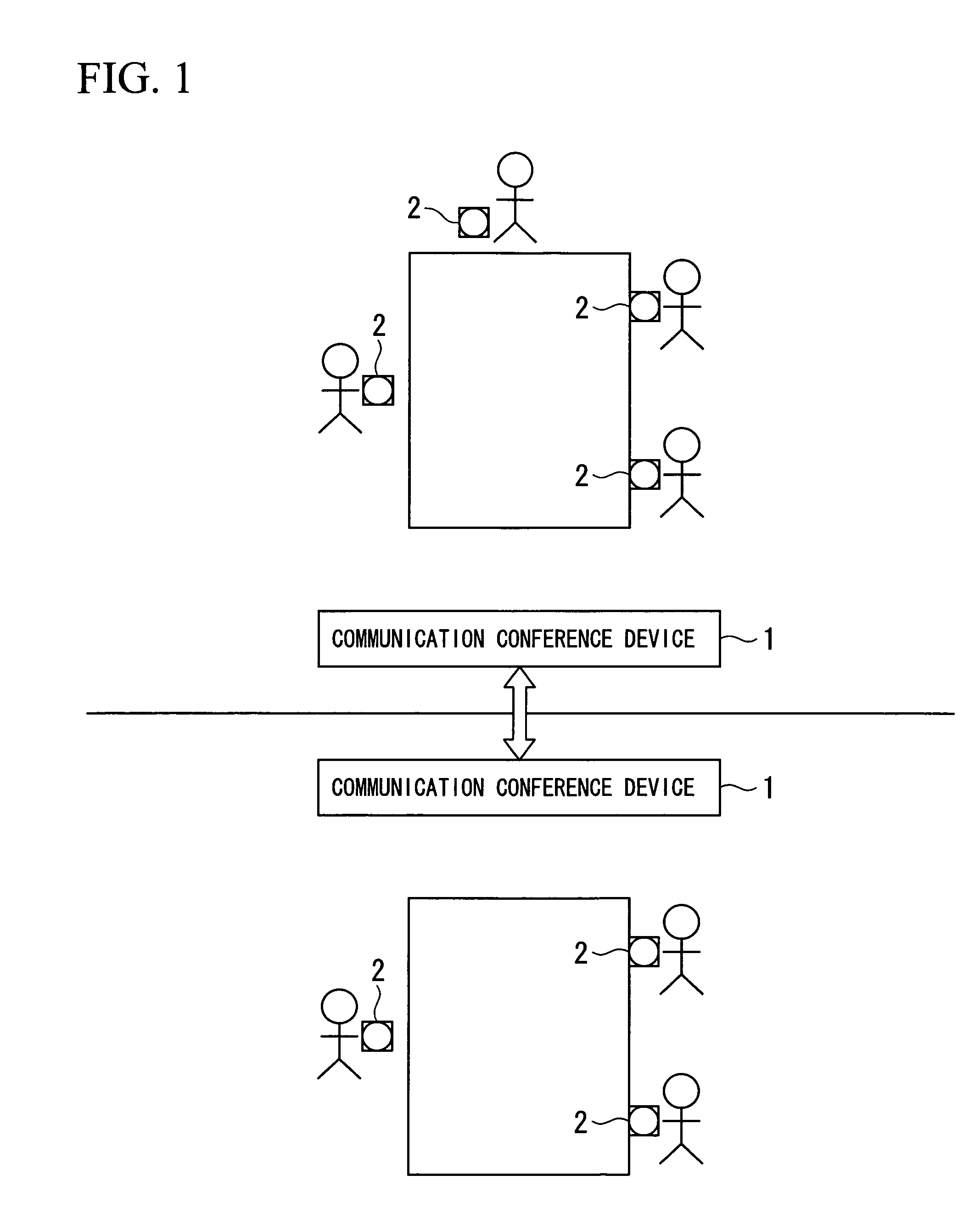
[0030]FIG. 1 is schematic diagram showing a configuration of a communication conference system according to an embodiment of the present invention. As shown in FIG. 1, this communication conference system comprises; communication conference devices 1 that are installed respectively in a plurality of conference rooms, and terminal units 2 that are carried by respective conference participants.

[0031]The communication conference devices 1 are installed in the respective conference rooms. The communication conference devices 1 are respectively connected via a network (LAN or Internet) or a telephone line. The terminal units 2 are remote controllers that are carried by all conference participants. A conference participant uses this terminal unit 2 to notify the commencement of a conference. This terminal unit 2 may be carried by each of conference participants, or it may be installed on a desk. Moreover, it is not necessary to provide terminal units 2 for all conference participants, and...


PUM


Abstract

In an audio transmission system, a control section of a communication conference device emits measurement sound waves from a loudspeaker array to a terminal unit and measures the time until a response is received, thereby detecting the position of the terminal unit. The control section sets directivity characteristics so that microphone sensitivity of the microphone array is brought to point to the position of the terminal unit, and sends the collected audio to another communication conference device. In a communication conference device on the reception side, the directivity characteristic of the loudspeaker array is set so that the received audio appears as if it was emitted from the position of the terminal unit on the transmission side.

Description

[0001]This application is the National Phase of International Application PCT / JP2006 / 304994, filed Mar. 14, 2006 which designated the U.S. and that International Application was not published under PCT Article 21(2) in English.TECHNICAL FIELD[0002]The present invention relates to an audio transmission system, in particular, to an audio transmission system that detects a position of a sound source and performs sound field control to create a high level of presence.[0003]Priority is claimed on Japanese Patent Application No. 2005-199683, filed Jul. 8, 2005, the content of which is incorporated herein by reference.BACKGROUND ART[0004]In general, a communication conference system is configured such that audio of conference participants is collected by a plurality of microphones, and is mixed and then transmitted. On the reception side, the audio is reproduced from all of loudspeakers at an equal level of sound volume and phase. In the case of such a communication conference system, the ...

Claims


Application Information

Patent Timeline
Patent Type & Authority Patents(United States)
IPC IPC(8): H04R5/02H04M3/42
CPCH04M3/56H04M3/568H04R1/403H04R1/406H04S7/302H04M7/0093H04R2430/20H04S2400/11
Inventor IWASAKI, YASUTAKA
Owner YAMAHA CORP
Why Eureka
Try Eureka