
System and method for reducing pain in a high-voltage lead impedance check procedure using DC voltage or current in an implantable medical device

a high-voltage lead impedance and check procedure technology, applied in the field of high-voltage lead impedance check in implanted medical devices, can solve problems such as increasing patient stress

Active Publication Date: 2012-06-26
PACESETTER INC
View PDF23 Cites 13 Cited by
  • Summary
  • Abstract
  • Description
  • Claims
  • Application Information

AI Technical Summary

Benefits of technology

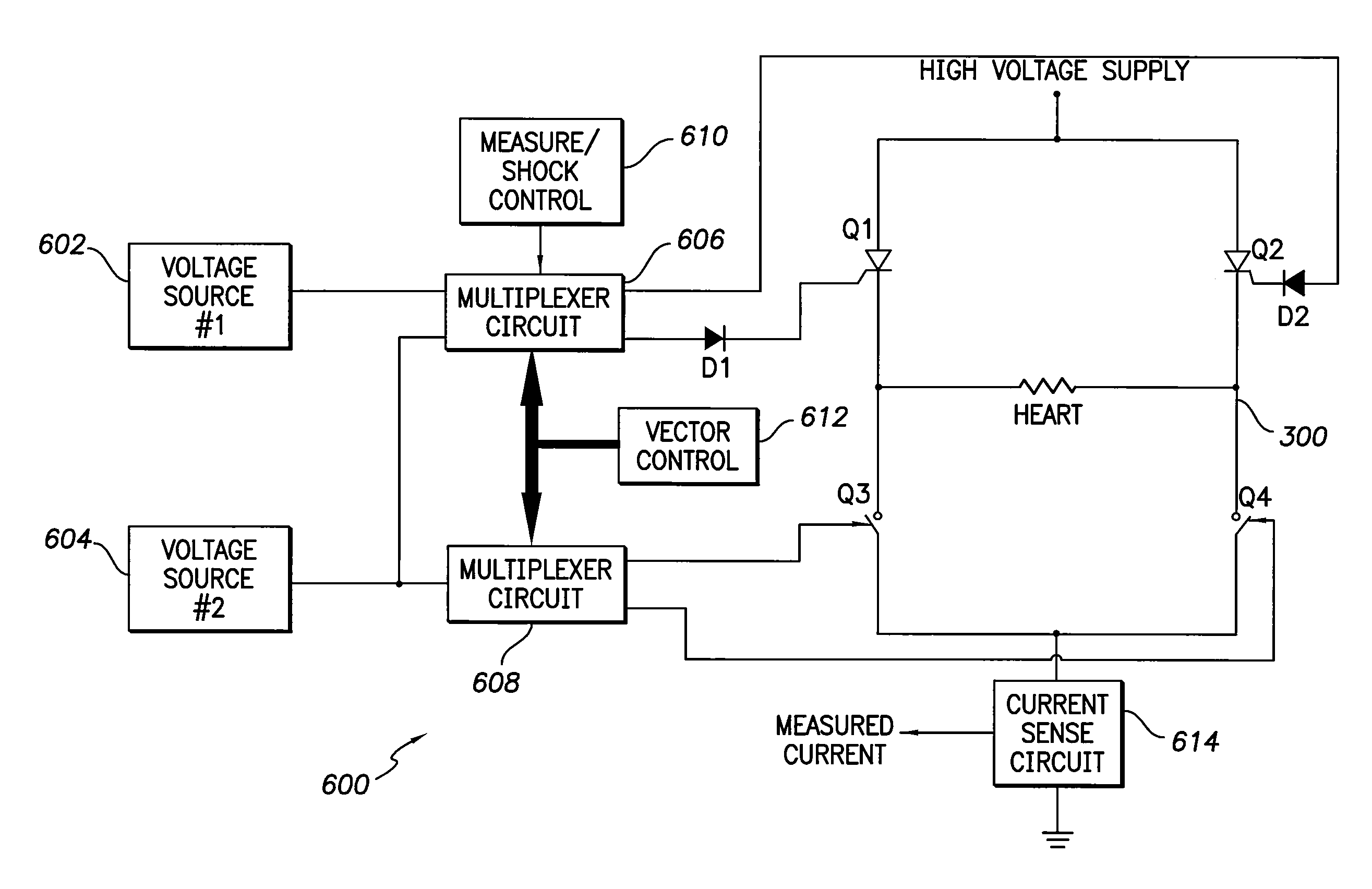
[0006]Constant voltage or current injected through high-voltage leads of the IMD can be used to determine the impedance. This is made possible through the use of thyristors, such as triacs or silicone controlled rectifiers (“SCRs”) for the upper switching components in an H-bridge. Current (or voltage) may be applied to the gate of the thyristor from a ground-referenced source. This current then passes from the gate to the cathode and out to the patient. By keeping the current sufficiently low, the thyristors will not conduct from the anode to the cathode.

Problems solved by technology

An HVLI check (“HVLIC”) must be performed periodically to ensure lead integrity, causing discomfort and increased stress of the patient.

Method used


Image

  • System and method for reducing pain in a high-voltage lead impedance check procedure using DC voltage or current in an implantable medical device
  • System and method for reducing pain in a high-voltage lead impedance check procedure using DC voltage or current in an implantable medical device
  • System and method for reducing pain in a high-voltage lead impedance check procedure using DC voltage or current in an implantable medical device

Examples


Embodiment Construction

[0020]While specific configurations and arrangements are discussed, it should be understood that this is done for illustrative purposes only. A person skilled in the pertinent art will recognize that other configurations and arrangements can be used without departing from the spirit and scope of the present invention. It will be apparent to a person skilled in the pertinent art that this invention can also be employed in a variety of other applications.

A. Implantable Medical Devices

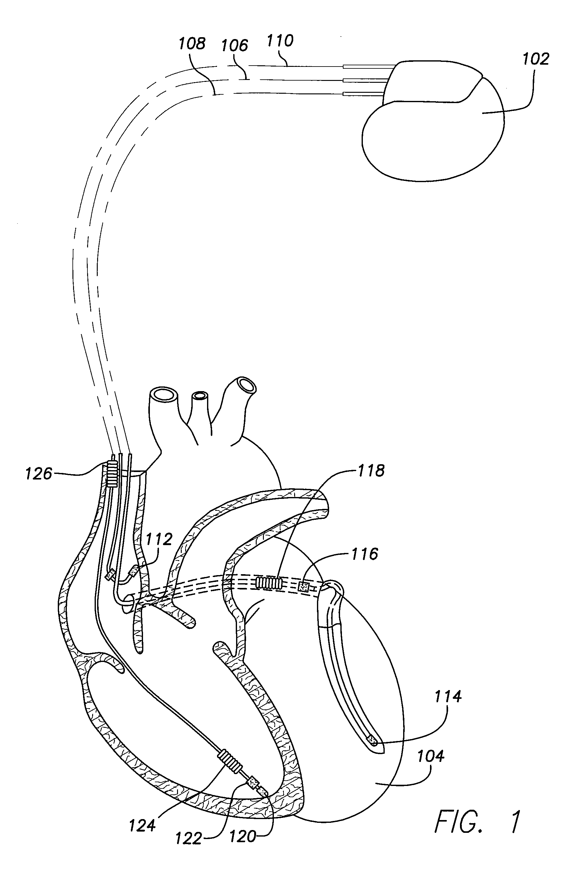
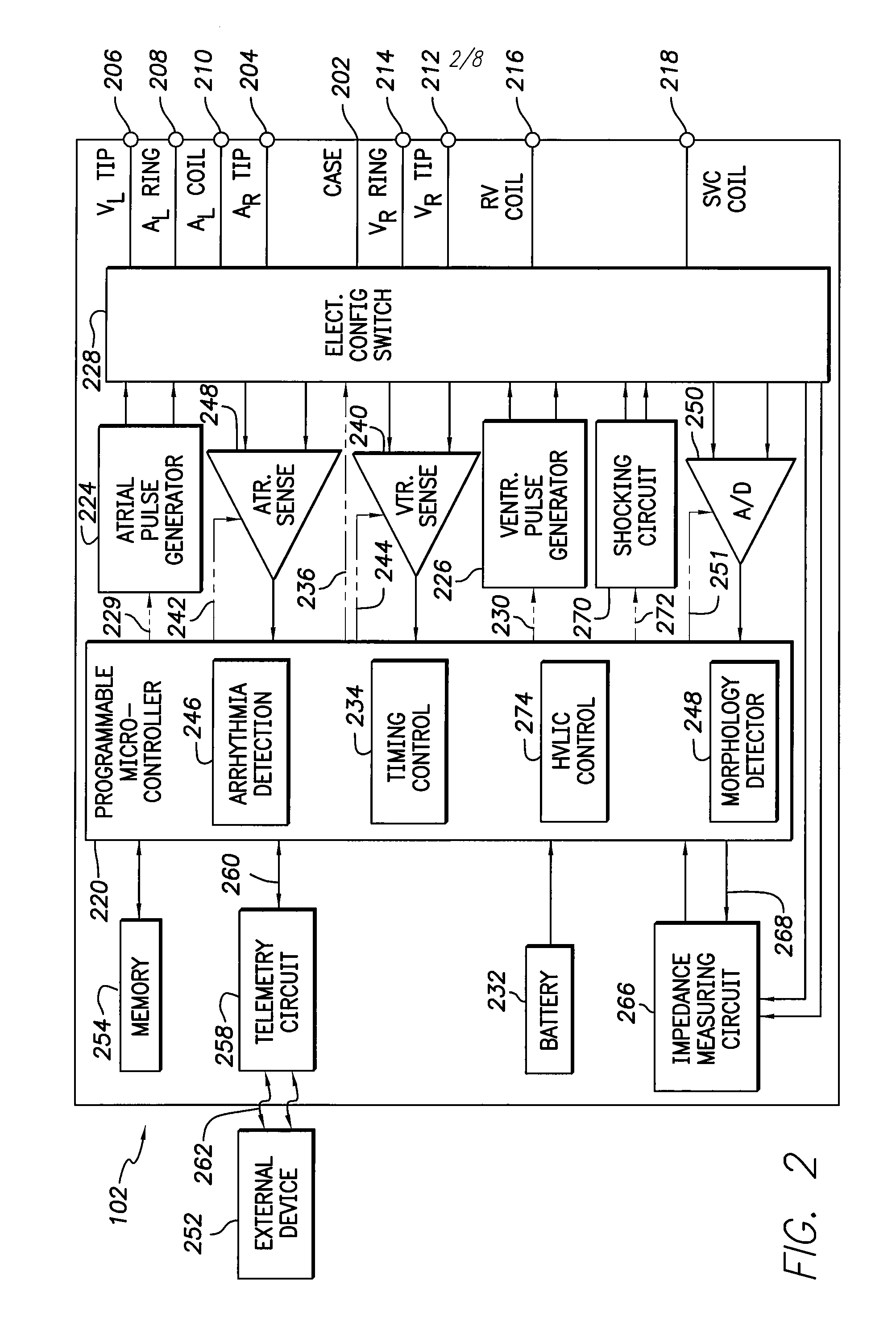
[0021]Implantable medical devices include, for example and without limitation, pacemakers, pulse generators, and cardioverter defibrillators. The term “implantable medical device,” or simply “IMD,” is used herein to refer to, non-exclusively and without limitation, any pacemaker, pulse generator, or cardioverter defibrillator. As used herein, the term IMD also includes other implantable devices such as artificial organs, insulin pumps, drug delivery devices, and other implanted devices for sensing physiol...


PUM


Abstract

Constant voltage or current is applied to high-voltage leads to determine impedance across medical device leads. Thyristors are used for upper switching components in an H-bridge. Current is sourced into a thyristor's gate from a ground-referenced source. This current then passes from the gate to the cathode and out to the patient. By keeping the current sufficiently low, the thyristors will not conduct from the anode to the cathode. Current passes through the thyristor, lead and patient and is sensed as it returns from the other lead. The sensed current is used to regulate the injected current. Pulses of constant current on the order of tens of milliamperes can be injected and the resulting voltage can be measured. Alternatively, a constant voltage can be applied and the resulting current can be measured to determine lead impedance.

Description

BACKGROUND OF THE INVENTION[0001]1. Field of the Invention[0002]The present invention is related to high-voltage lead impedance checks in implanted medical devices, as well as circuitry used in the devices.[0003]2. Background Art[0004]It is of critical importance in an implantable medical device (“IMD”) that appropriate high-voltage lead impedance (“HVLI”) be monitored. Too high of an impedance indicates that there may be a problem with lead integrity or placement and revision surgery may be indicated. Methods in use today are not painless and can be felt by the patient. An HVLI check (“HVLIC”) must be performed periodically to ensure lead integrity, causing discomfort and increased stress of the patient.[0005]Therefore, what is needed is a method and apparatus for reducing or eliminating pain caused by HVLIC.BRIEF SUMMARY OF THE INVENTION[0006]Constant voltage or current injected through high-voltage leads of the IMD can be used to determine the impedance. This is made possible thr...

Claims


Application Information

Patent Timeline
Patent Type & Authority Patents(United States)
IPC IPC(8): A61B5/05
CPCA61N1/3925
Inventor MOULDER, J. CHRISTOPHERISAAC, GEORGE I.SILVIAN, SERGIU
Owner PACESETTER INC
Learn More