Aircraft sensor anticipator system

a sensor and anti-aircraft technology, applied in the field of aircraft control systems and methods, can solve the problems of unsatisfactory autopilot performance and add to the cost and labor required to complete the retrofi

Active Publication Date: 2012-06-26
GARMIN INT
View PDF8 Cites 17 Cited by
  • Summary
  • Abstract
  • Description
  • Claims
  • Application Information

AI Technical Summary

Problems solved by technology

This can be problematic when the AHRS and / or ADC being interfaced with the autopilot system have different dynamics, including latency or time lag properties, than the original analog attitude sensor or the other model of the digital AHRS.
The time delay from the AHRS may result in undesirable autopilot performance if the associated vertical gyro is replaced by the AHRS.
However, altering the autopilot system adds to the cost and labor required to complete the retrofit.

Method used


Image

  • Aircraft sensor anticipator system
  • Aircraft sensor anticipator system
  • Aircraft sensor anticipator system

Examples


Embodiment Construction

[0019]The following detailed description of various embodiments of the invention references the accompanying drawings that illustrate specific embodiments in which the invention can be practiced. The embodiments are intended to describe aspects of the invention in sufficient detail to enable those skilled in the art to practice the invention. Other embodiments can be utilized and changes can be made without departing from the scope of the present invention. The following detailed description is, therefore, not to be taken in a limiting sense. The scope of the present invention is defined only by the appended claims, along with the full scope of equivalents to which such claims are entitled.

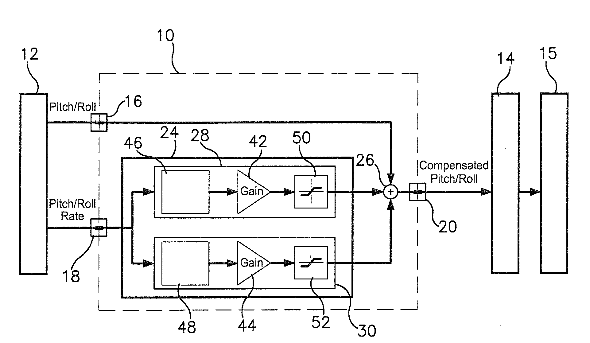
[0020]FIG. 1 illustrates an exemplary embodiment of an apparatus 10 for anticipating or estimating future pitch and / or roll angles of an aircraft to compensate for a time delay of a signal processed or calculated by a flight instrumentation system 12. The apparatus 10 may receive signals from the ...


PUM


Abstract

An apparatus and method for estimating future pitch and roll angles of an aircraft to compensate for a time delay caused by a flight instrumentation system calculating the aircraft's pitch and roll. The apparatus may output signals to an aircraft autopilot system. The apparatus may comprise various inputs and outputs, at least one compensation module, and at least one addition module. The compensation module may multiply a gain value by the pitch rate of the aircraft and by the roll rate of the aircraft to determine a pitch compensation amount and a roll compensation amount. Then the pitch compensation amount may be added to the pitch of the aircraft, and the roll compensation amount may be added to the roll of the aircraft to solve for a compensated pitch and a compensated roll to send to the autopilot system.

Description

RELATED APPLICATION[0001]This Application, under the provisions of 35 U.S.C. §119(e), claims the benefit of priority to U.S. Provisional Application Ser. No. 61 / 082,263, filed Jul. 21, 2008, entitled “AIRCRAFT SENSOR ANTICIPATOR APPARATUS” the disclosure of which is incorporated herein by reference in its entirety.BACKGROUND OF THE INVENTION[0002]1. Field of the Invention[0003]Embodiments of the present invention relate to aircraft control systems and methods. More particularly, embodiments of the present invention relate to a method and apparatus for estimating future pitch and roll angles of an aircraft.[0004]2. Description of the Related Art[0005]The attitude (or angular orientation) of a vehicle encompasses both its pitch angle and roll angle (or bank angle). For an aircraft, the pitch angle generally refers to the nose-up / nose-down angle, and the roll angle generally refers to the angle of the wings (e.g. left wing up / right wing down or left wing down / right wing up; similar con...

Claims


Application Information

Patent Timeline
Patent Type & Authority Patents(United States)
IPC IPC(8): G05D1/00
CPCG01C21/165G01C21/1654
Inventor MCLOUGHLIN, FRANK A.LI, XI
Owner GARMIN INT
Why Eureka
Try Eureka