Flush mount panels with multiple aligned receiving brackets

a technology of receiving brackets and flush mounts, which is applied in the direction of girders, electrical apparatus casings/cabinets/drawers, loudspeakers, etc., can solve the problems of ineffective mounting of components in positions other than along the ceiling joist, and the difficulty of arranging or evenly spacing multiple components, etc., to achieve the effect of convenient installation

Active Publication Date: 2012-07-03
DANA INNOVATIONS
View PDF13 Cites 7 Cited by
  • Summary
  • Abstract
  • Description
  • Claims
  • Application Information

AI Technical Summary

Benefits of technology

[0010]Two, three, or more receivers can be affixed to openings in the panel, which typically extend from a front side of the panel to the back side of the panel. Receivers can range from a simple rim disposed on the inside of the opening to an extensive bracket and housing extending out the back of the panel. In any event, completed assemblies preferably have little or no discernable gap between the panel and the receiver. This can be accomplished in any suitable manner, including for example, accurately cutting the opening into which the receiver is installed and then gluing the receiver to the panel. Where the panel comprises a formed substance such as drywall, another option is to form the panel around the receiver.
[0012]Panels are typically installed into the wallboard by first approximating the edges of the panel with the edges of the wallboard. “Approximating” is defined herein to mean bringing the edges near or towards one another so that the junction or gap between the edges is less than 10 mm (0.394 in), 5 mm (0.197 in), or even 2 mm (0.079 in). If the junction or gap between the edges is larger, a buffer can be attached to the edge of the panel before installation, or one or more shims can be installed into the junction. The junction can then be concealed using a suitable construction method, for example taping or plastering over the junction. Providing a pre-fabricated panel designed to accept specific components greatly facilitates installation by eliminating the need for on-site precision measurements.

Problems solved by technology

However, since the cutouts are performed at the job site, it can be difficult to line up or evenly space multiple components.
Even where the task can be performed, there is a considerable amount of work exerted in taking measurements and making minor adjustments.
Weber, however, is ineffective at attaching components in positions other than along a ceiling joist, and Eichner cannot be used for recessed components integrated with the existing wall or ceiling.
Attaching the components directly to the support beam means that the centerlines of the components are out of alignment with one another.
However, adding additional support beams for each mounted component is time consuming, labor intensive, and is still prone to errors if the installer makes a measurement mistake.
However, building an entire wall in advance at an off-site location is very often impractical, especially when making a late installation decision after a wall has been installed.
Additionally, none of the prior art teaches arranging mounted components that achieve a flush-mount appearance in walls, ceilings, and other structures, in which little or even no finishing is required around the periphery of the opening.

Method used


Image

  • Flush mount panels with multiple aligned receiving brackets
  • Flush mount panels with multiple aligned receiving brackets
  • Flush mount panels with multiple aligned receiving brackets

Examples


Embodiment Construction

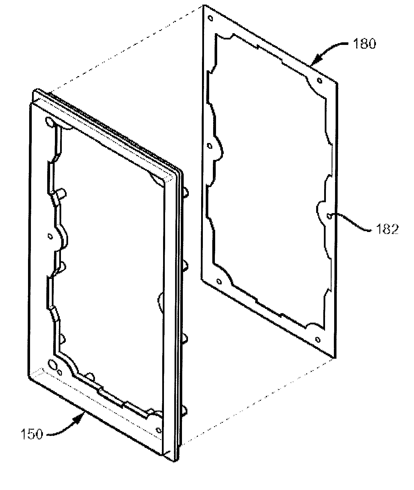
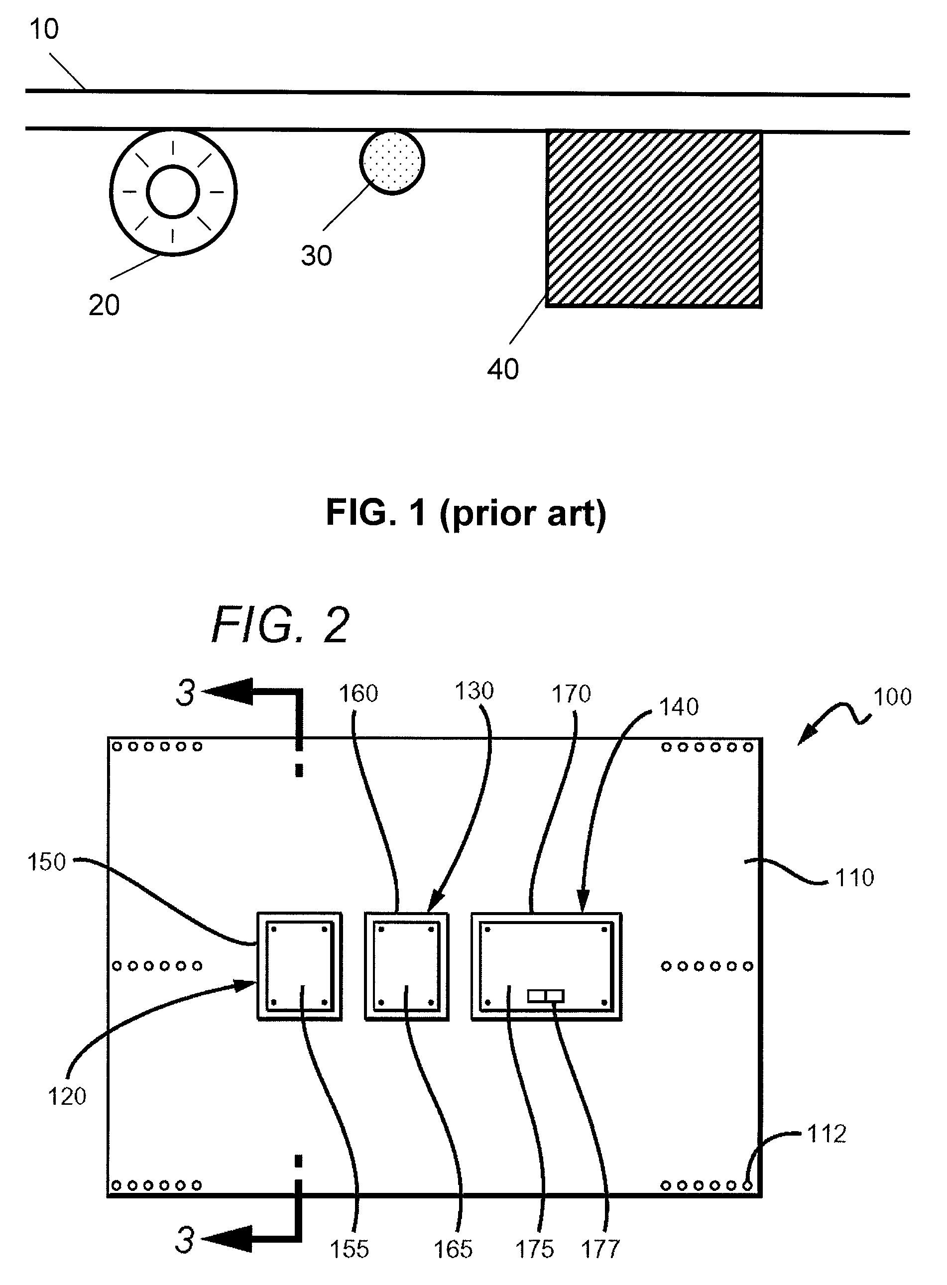
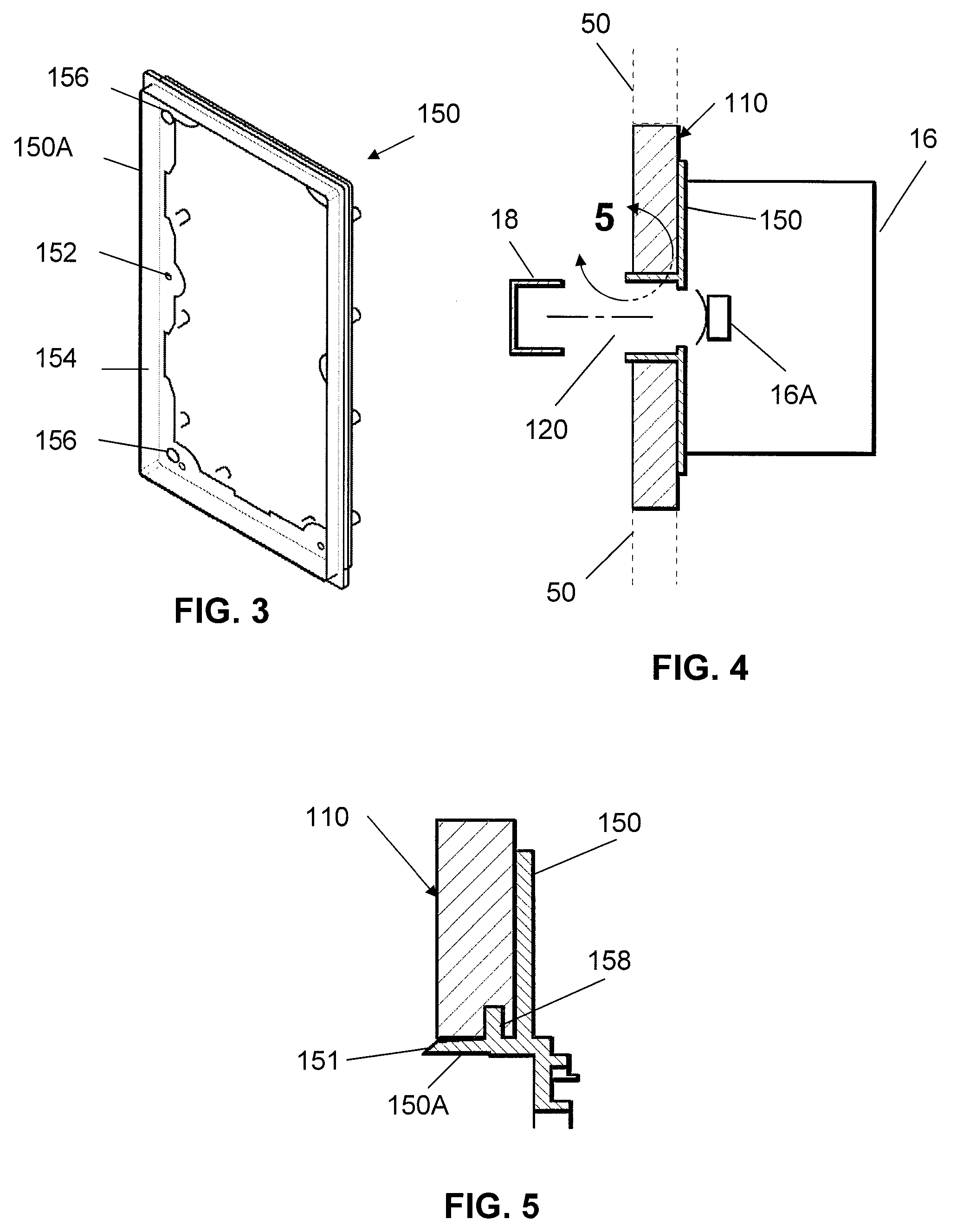
[0040]In FIG. 2 a component mounting apparatus 100 generally includes a panel 110 with openings 120, 130, and 140. Each opening 120, 130, and 140, has a bracket 150, 160, and 170, and a spackle shield 155, 165, and 175, respectively. It should be appreciated that while each bracket is sized and dimensioned to hold a specific component, the brackets could be identical to one another to create a “universal bracketing system” that can hold components of various sizes.

[0041]Panel 110 is a piece of gypsum board, wood, plastic, or other material (or combination of materials) sufficiently strong to support a speaker or other desired component between two studs of a wall, or joists or other supports in a ceiling. Where plywood is used as the panel material, for example, the panel might be as thin as ¼″ (6.35 mm), but would more preferably measure at least ½″ (12.7 mm) or ⅜″ (19.05 mm). Preferred materials include wallboard, Medium Density Fiberboard (MDF), High Density Fiberboard (MDF), Acr...


PUM


Abstract

A panel with multiple openings and brackets can be used to flush-mount multiple components in a wallboard. The panel is installed flush with the wallboard and the junction between the panel and the wallboard is plastered or drywalled to create a uniform appearance. Wall-mounted components can then be installed into the brackets into openings that have been pre-measured and cut to ensure that the components are aligned with precision relative to one another before installation even begins.

Description

[0001]This application is a continuation-in-part of non-provisional application Ser. No. 11 / 954,667 filed Dec. 12, 2007 now U.S. Pat. No. 7,461,483. Ser. No. 11 / 954,667 is a continuation-in-part of non-provisional application Ser. No. 11 / 566,365 filed Dec. 4, 2006 now U.S. Pat. No. 7,699,138, and also claims priority to (1) provisional application Ser. No. 60 / 950,237 filed Jul. 17, 2007 and (2) International application ser. no. PCT / US07 / 16404 filed Jul. 19, 2007. Ser. No. 11 / 566,365 claims priority to provisional application Ser. No. 60 / 825,162 filed Sep. 11, 2006. PCT / US07 / 16404 claims priority to (1) non-provisional application Ser. No. 11 / 548,381 filed Oct. 11, 2006, (2) provisional application 60 / 825,162 filed Sep. 11, 2006, and (3) provisional application 60 / 950,237 filed Jul. 17, 2007. All prior applications are incorporated by reference in their entirety.FIELD OF THE INVENTION[0002]The field of the invention is wall and ceiling receptacles.BACKGROUND[0003]Plasma screens, spe...

Claims


Application Information

Patent Timeline
Patent Type & Authority Patents(United States)
IPC IPC(8): E06B1/04
CPCH02G1/00H02G3/123H04R1/025H02G2200/30H04R2201/021H04R2499/13
Inventor STRUTHERS, SCOTTCALL, RAYSPENCER, GEOFFFETTER, GREG
Owner DANA INNOVATIONS
Why Eureka
Try Eureka