
Rotary drill bits with protected cutting elements and methods

a technology of cutting elements and drill bits, applied in earth drilling, cutting machines, instruments, etc., can solve the problems of not protecting primary cutters and effective control of cutting rate, and achieve the effects of reducing or eliminating damage to cutting surfaces and/or cutting edges, prolonging the life of downhole drilling associated rotary drill bits, and efficient controlling penetration ra

Active Publication Date: 2012-07-03
HALLIBURTON ENERGY SERVICES INC
View PDF15 Cites 36 Cited by
  • Summary
  • Abstract
  • Description
  • Claims
  • Application Information

AI Technical Summary

Benefits of technology

[0008]In accordance with teachings of the present disclosure, rotary drill bits and other downhole tools used to form a wellbore may be provided with cutting elements having respective protectors operable to control depth of a cut formed by each cutting element in adjacent portions of a downhole formation and control rate of penetration of an associated rotary drill bit. For some applications, secondary cutting elements having respective protectors may be combined with primary cutting elements having respective protectors to prolong downhole drilling life of an associated rotary drill bit.
[0009]Another aspect of the present disclosure may include substantially reducing and / or eliminating damage to cutting elements while drilling a wellbore in a downhole formation having hard materials. For some applications such cutting elements may have dual cutting surfaces and associated cutting edges. Controlling depth of each cut or kerf formed in adjacent portions of a downhole formation in accordance with teachings of the present disclosure may provide enhanced axial stability and lateral stability during formation of a wellbore. Steerability and tool face controllability of an associated rotary drill bit may also be improved.
[0011]Technical benefits of the present disclosure may include, but are not limited to, controlling depth of cut of cutting elements disposed on a rotary drill bit, efficiently controlling rate of penetration of the rotary drill bit and / or providing secondary cutting elements operable to prolong downhole drilling life of an associated rotary drill bit. Forming rotary drill bits and associate cutting elements in accordance with teachings of the present disclosure may substantially reduce or eliminate damage to cutting surfaces and / or cutting edges associated with such cutting elements.
[0012]Further technical benefits of the present disclosure may include, but are not limited to, eliminating or minimizing impact damage to primary cutters or major cutters, increasing bit life by providing secondary cutters operable to function as primary cutters or major cutters when associated primary cutters experience a designed amount of wear, increased stability of an associated rotary drill bit both axially and radially relative to a bit rotation axis and improving directional drilling control by more efficiently avoiding damage to associated gage cutters.

Problems solved by technology

For such drilling operations, the secondary cutters may not effectively control rate of penetration and may not protect the primary cutters.

Method used


Image

  • Rotary drill bits with protected cutting elements and methods
  • Rotary drill bits with protected cutting elements and methods
  • Rotary drill bits with protected cutting elements and methods

Examples


Embodiment Construction

[0057]Preferred embodiments of the present disclosure and various advantages may be understood by referring to FIGS. 1-22B of the drawings. Like numerals may be used for like and corresponding parts in the various drawings.

[0058]The terms “rotary drill bit” and “rotary drill bits” may be used in this application to include various types of fixed cutter drill bits, drag bits, matrix drill bits and PDC drill bits. Cutting elements and blades incorporating features of the present disclosure may also be used with reamers, near bit reamers, and other downhole tools associated with forming a wellbore.

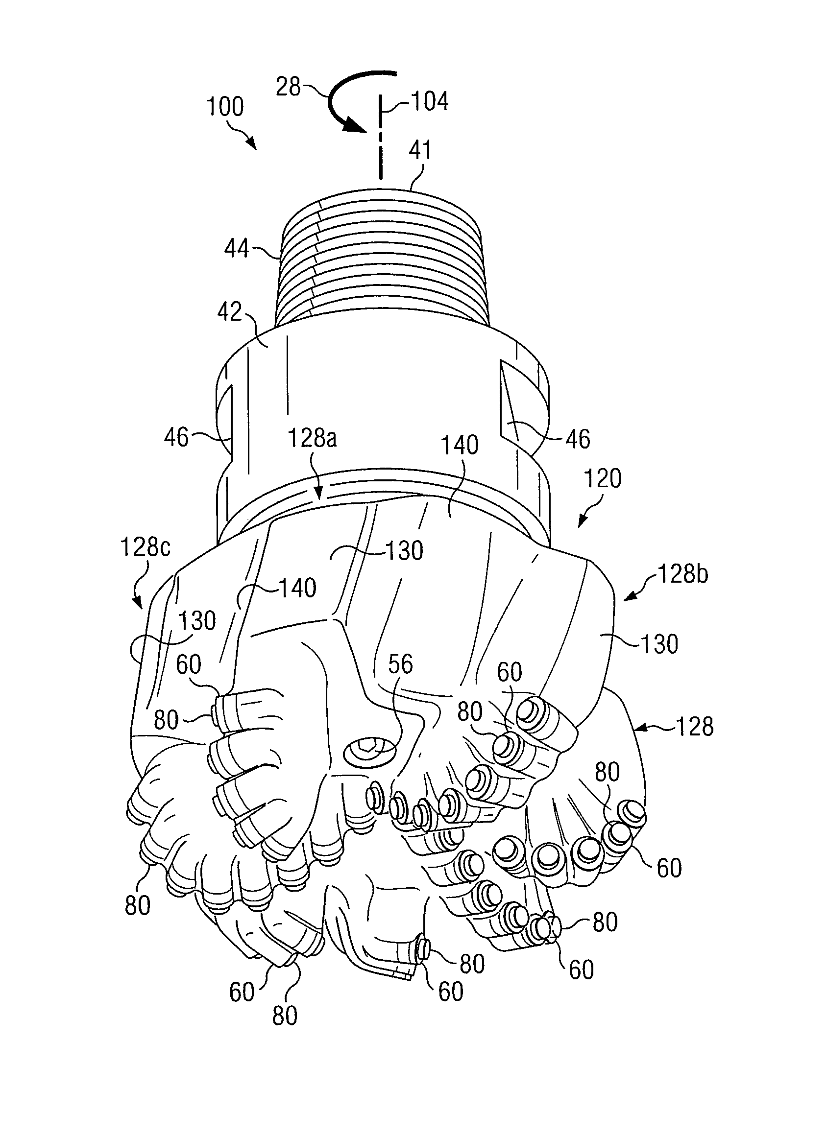
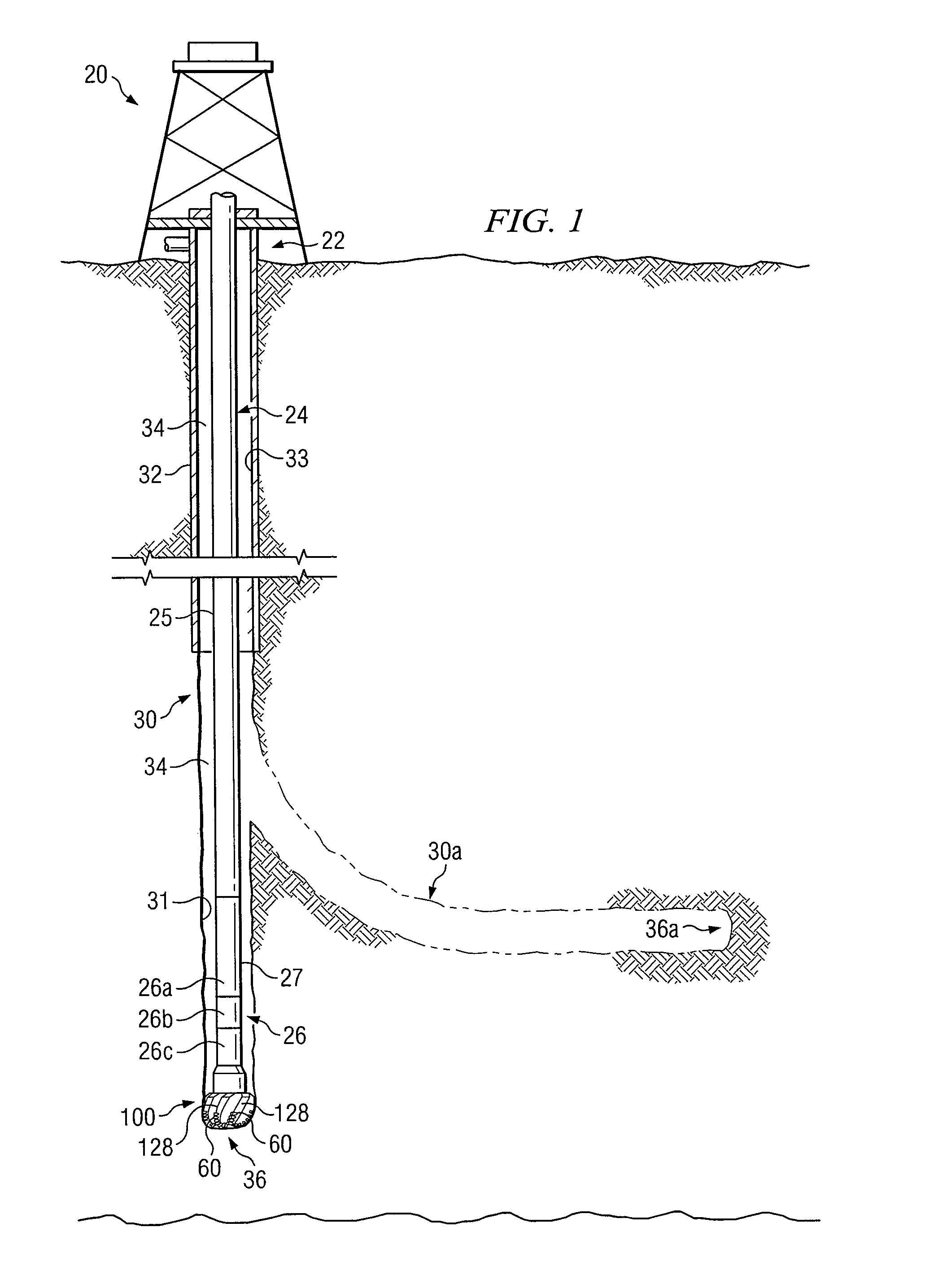
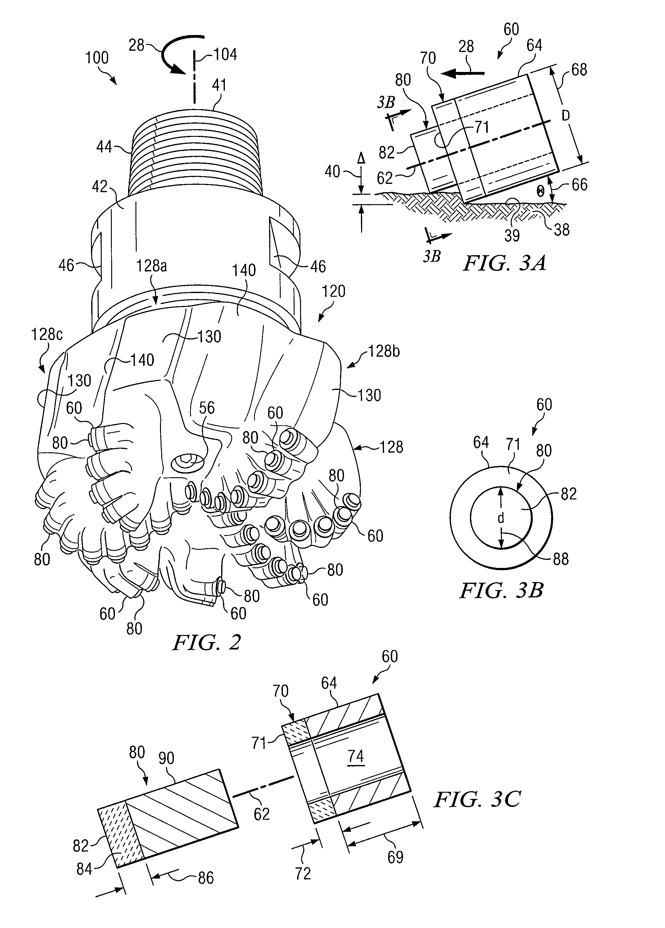
[0059]Rotary drill bits incorporating teachings of the present disclosure may have many different designs and configurations. Rotary drill bits 100, 100a and 100b as shown in FIGS. 1, 2, 17, and 21 represent only some examples of rotary drill bits and cutting elements which may be formed in accordance with teachings of the present disclosure.

[0060]The terms “cutting element” and “cutting elem...


PUM


Abstract

A rotary drill bit with cutting elements operable to control depth of cut and rate of penetration during formation of a wellbore are provided. Respective sets of secondary cutting elements and primary cutting elements may also be disposed on exterior portions of a rotary drill bit. A number of blades may extend from exterior portions of the drill bit with a number of cutting elements disposed on exterior portions of each blade. Each cutting element may include a substrate with a cutting surface disposed thereon. A respective protector may extend from the cutting surface of one or more cutting elements to limit depth of penetration of the associated cutting element into adjacent portions of a downhole formation and / or to control rate of penetration of an associated rotary drill bit.

Description

CROSS REFERENCE TO RELATED APPLICATIONS[0001]This application is a U.S. National Stage Application of International Application No. PCT / US2008 / 052468 filed Jan. 30, 2008, which designates the United States of America, and claims the benefit of U.S. Provisional Application No. 60 / 887,459, filed Jan. 31, 2007, the contents of which are hereby incorporated by reference in their entirety.TECHNICAL FIELD[0002]The present disclosure is related to downhole tools used to form wellbores including, but not limited to, rotary drill bits and other downhole tools having cutting elements and more particularly to improving downhole performance by controlling depth of cut for each cutting element and rate of penetration for an associated drill bit.BACKGROUND OF THE DISCLOSURE[0003]Various types of rotary drill bits, reamers, stabilizers and other downhole tools may be used to form a borehole in the earth. Examples of such rotary drill bits include, but not limited to, fixed cutter drill bits, drag ...

Claims


Application Information

Patent Timeline
Patent Type & Authority Patents(United States)
IPC IPC(8): E21B10/36E21B10/46E21B10/43
CPCE21B10/55E21B10/567E21B10/5735
Inventor CHEN, SHILINKING, WILLIAM W.
Owner HALLIBURTON ENERGY SERVICES INC
Learn More