
Video endoscope

a technology of endoscope and endoscope, which is applied in the field of video endoscope, can solve the problems of excessively difficult for users to orient themselves/herself, difficult device handling, and difficult spatial orientation for users, and achieve the effect of preventing horizontal tilting

Active Publication Date: 2012-07-03
DIGITAL ENDOSCOPY
View PDF9 Cites 17 Cited by
  • Summary
  • Abstract
  • Description
  • Claims
  • Application Information

AI Technical Summary

Benefits of technology

"The present invention provides a video endoscope with a simple way to correct the image position during rotation and prevent horizontal tilting. The endoscope has a rigid endoscope tube with an image sensor located at the distal end of the endoscope shaft. A rotating wheel with permanent magnets is arranged on the proximal end of the endoscope shaft, and Hall sensors are connected to the image sensor. The rotating wheel is rotated by the user, and the position of the rotating wheel is detected by the Hall sensors. The detected position is then used to evaluate the image position and display it on the monitor. The invention allows for easy one-handed operation of the endoscope and prevents damage to the optical system during cleaning. The viewing direction and angle can also be displayed on the monitor for better orientation. A gravitation sensor can be added to the endoscope for accurate positioning."

Problems solved by technology

Another situation arises during the axial rotation of an endoscope with a sideways viewing optical system, because the image position on the screen changes during the orientation, which makes it extraordinarily difficult for the user to orient himself / herself.
As a result of rotation of the image horizon, also referred to as horizontal tilting, the spatial orientation is made extraordinarily difficult for the user.
However, such a device is not easy to handle, because of the separation between the camera head and the optical system.
However, the drawback here is the not inconsiderable mechanical effort, which necessarily limits the product life of such a system, which must indeed be cleaned at regular intervals by steam sterilization.
In addition, in such a system, the length of the element that is to be bent leads to a restriction of the visibility conditions in narrow cavities and body cavities, such as, for example, in the application in laparoscopy.
Furthermore, bending over an angle of more than 90° with respect to the above-mentioned horizontal tilting makes it difficult for the user to orient himself / herself.
What is not appreciated by the prior art is that the two-shaft solution is particularly susceptible to breakdown, because of the shafts that have to be rotated with respect to each other, and particularly because of the required steam sterilization, leading not only to a cost increase, but also to a significantly shorter product life for such an apparatus.

Method used


Image

  • Video endoscope
  • Video endoscope
  • Video endoscope

Examples


Embodiment Construction

[0032]Reference will now be made in detail to several embodiments of the invention that are illustrated in the accompanying drawings. Wherever possible, same or similar reference numerals are used in the drawings and the description to refer to the same or like parts or steps. The drawings are in simplified form and are not to precise scale. For purposes of convenience and clarity only, directional terms, such as top, bottom, up, down, over, above, and below may be used with respect to the drawings. These and similar directional terms should not be construed to limit the scope of the invention in any manner. The words “connect,”“couple,” and similar terms with their inflectional morphemes do not necessarily denote direct and immediate connections, but also include connections through mediate elements or devices.

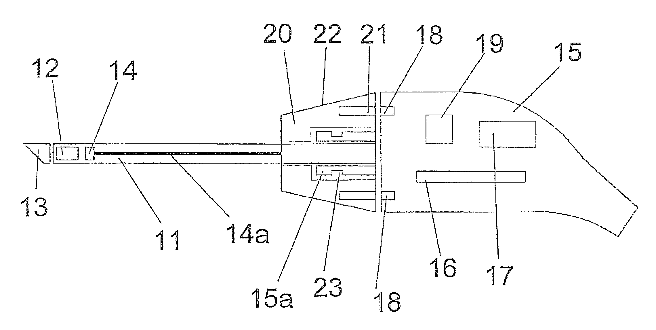
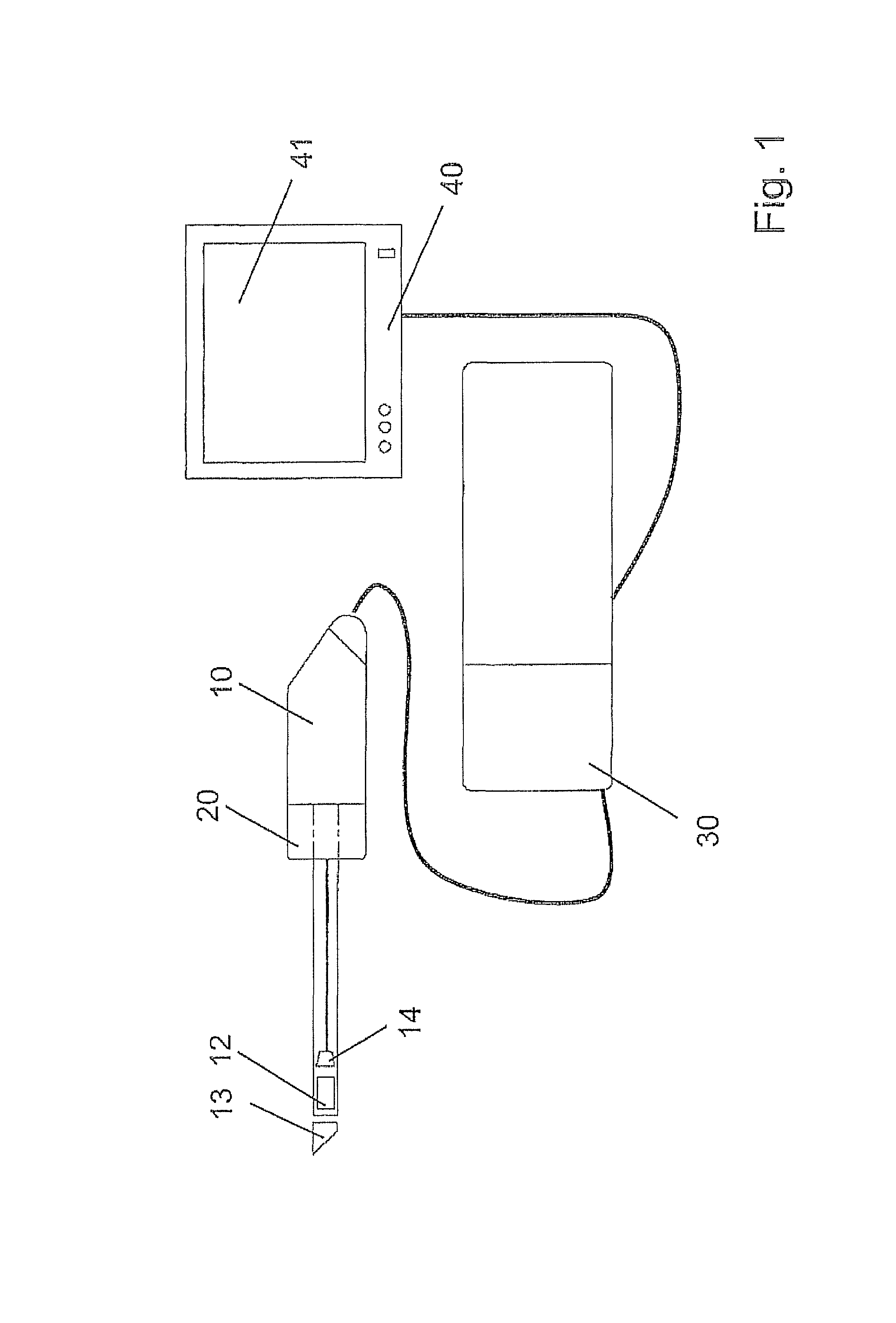
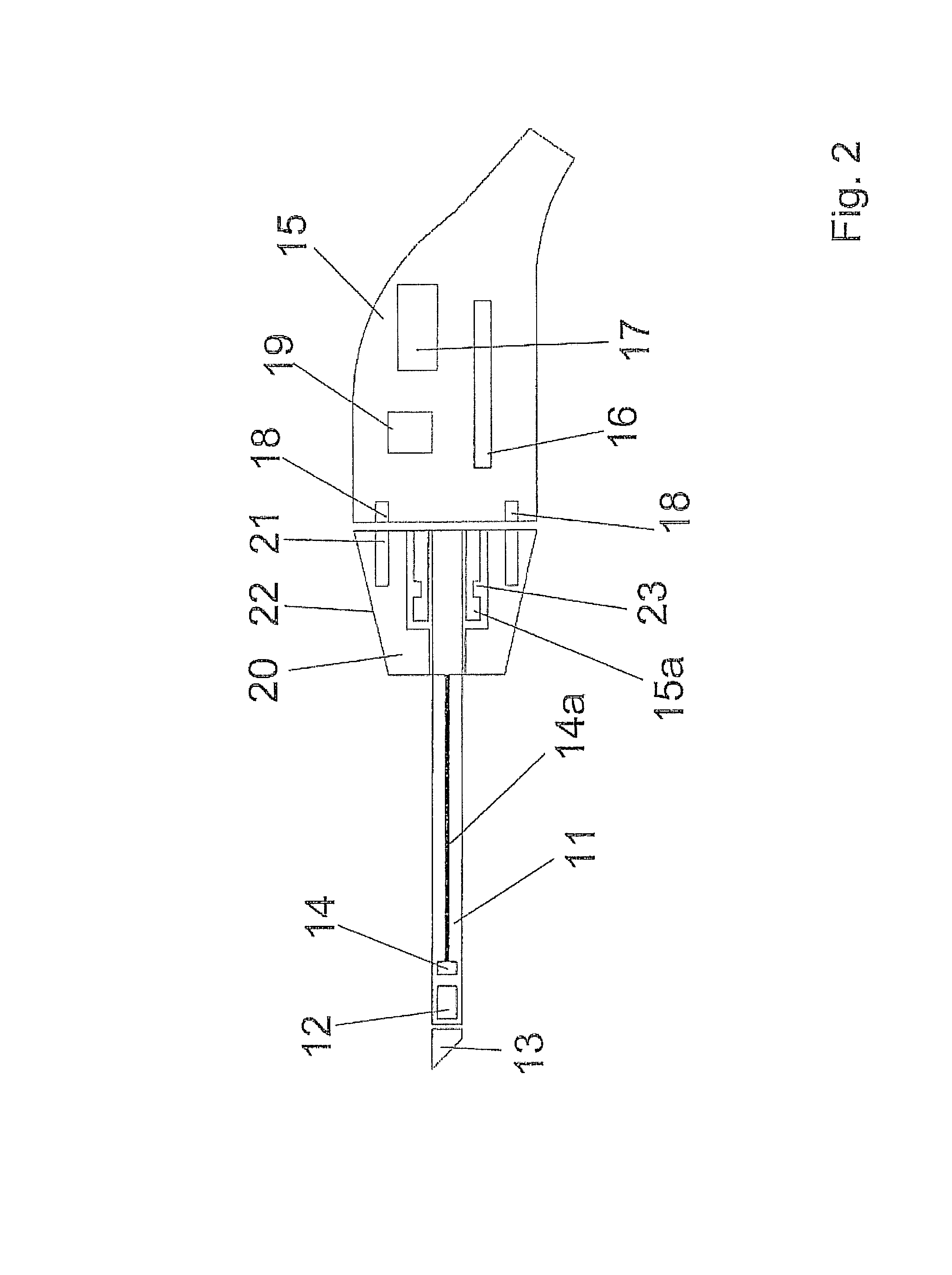
[0033]The overall circuit for a video endoscope 10 according to the invention, which is connected via a control apparatus 30 to the monitor 40, is represented in FIG. 1.

[0034...


PUM


Abstract

The invention is a sideways looking video endoscope which offers a rigid endoscope tube. The optical system has one prism, and an image sensor located behind the optical system, provided on the distal end of the endoscope shaft. On the proximal end of the shaft, a knurled wheel is arranged so as to rotate freely. This wheel is provided with permanent magnets that are arranged at identical angular separations, and associated with Hall sensors located on the front face of the tool holder. The angular position of the rotatable wheel can thus be detected by means of the Hall sensors together with an electronic system that evaluates the signals, and displayed on a monitor. By turning the rotating wheel, the image can be rotated, thus correcting the image position when the endoscope is rotated, such that the viewing direction corresponds to the actual position of the object.

Description

CROSS REFERENCE TO RELATED APPLICATIONS[0001]This application is related to, and claims priority from, German Patent Application Serial No. 10 2008 057 734.0, filed Nov. 17, 2008, the entire contents of which is incorporated herein by reference.FIGURE SELECTED FOR PUBLICATION[0002]FIG. 2BACKGROUND OF THE INVENTION[0003]1. Field of the Invention[0004]The present invention relates to a video endoscope for use in diagnostic medicine, among other fields. More specifically, the present invention relates to an endoscope in which the image position can be corrected in a simple way during the rotation of the endoscope with a sideways looking optical system, and where horizontal tilting is prevented.[0005]2. Description of the Related Art[0006]Endoscopes, including particularly video endoscopes, allow the user to view body cavities, in a simple, minimally invasive way, for the purpose of diagnosis or also therapy. Such endoscopes are also referred to by the word technoscope or boroscope for ...

Claims


Application Information

Patent Timeline
Patent Type & Authority Patents(United States)
IPC IPC(8): A61B1/04A61B1/00
CPCA61B1/00177A61B1/00183A61B1/045A61B1/00009G02B23/2484H04N7/181A61B1/05A61B1/3132
Inventor HENZLER, MARC
Owner DIGITAL ENDOSCOPY
Learn More