Co-access bipolar ablation probe

a bipolar ablation and co-access technology, applied in the field of radio frequency ablation probes, can solve the problems of increasing the pain and discomfort of patients, painful burns, and currently existing co-access systems that do not work well with bipolar ablation electrodes, and achieves efficient and effective ablation

Active Publication Date: 2012-07-03
SCI MED LIFE SYST
View PDF27 Cites 7 Cited by
  • Summary
  • Abstract
  • Description
  • Claims
  • Application Information

AI Technical Summary

Benefits of technology

[0014]Although the present inventions should not be so limited in their broadest aspects, deployment of the electrodes of the proximal array out from the cannula windows allows the respective proximal and distal electrode arrays to be properly positioned in a targeted tissue region without having to readjust the cannula. To prevent the influx of tissue into the cannula lumen, e.g., during introduction of the cannula into the patient's body, the cannula may comprise one or more coverings disposed over the windows, in which case, the electrodes of the proximal array will be configured to extend through the covering(s) when deployed out from the respective windows. In an optional embodiment, the electrodes of the proximal array may be longitudinally staggered, e.g., to minimize the profile of the ablation probe and facilitating mounting of the electrodes onto the probe shaft. In this case, the cannula windows will likewise be staggered.
[0017]The method further comprises conveying ablation energy to the ablation probe to ablate the tissue region within the electrode arrays. The ablation energy can be delivered to both electrode arrays and returned using a neutral electrode, but is preferably conveyed between the electrode arrays to provide for a more efficient and effective ablation. In one method, the proximal electrode array is deployed into contact with a proximal portion of the tissue region, and the distal electrode array is deployed into contact with a distal portion of the tissue region, so that, e.g., the entire treatment region can be ablated during a single ablation procedure (i.e., without moving the cannula), or at the least, ablated using a minimal amount of ablation procedures. In optional methods, other medical elements, such as a biopsy probe, obturator, or chemotherapeutic agent, may be introduced through the cannula before the ablation probe has been introduced into the cannula or after the ablation probe has been removed from the cannula.

Problems solved by technology

Additionally, bipolar arrangements are generally safer for the physician and patient, since there is an ever-present danger that the physician and patient may become a ground in the monopolar arrangement, resulting in painful burns.
The multiple tissue insertions also increases the pain and discomfort suffered by the patient during this procedure.
While a co-access system works well for monopolar ablation electrodes, such as the monopolar LeVeen Needle Electrode™, the currently existing co-access systems would not work well with bipolar ablation electrodes, such as the dual-electrode arrays disclosed in U.S. Patent Publication 2002 / 0022864 and U.S. patent application Ser. No. 09 / 663,048.
To the extent that the electrode arrays must be re-navigated in order to ablate abnormal tissue that was not treated during the initial procedure, a main advantage of the co-access system will be lost—i.e., the cannula will no longer act as a place marker for properly locating the ablation probe, and unnecessary ablation procedures will have to be performed, increasing patient discomfort and increasing the time required to perform the procedure.
Notably, properly placement of the electrode arrays within the treatment region cannot be easily facilitated by merely modifying the length of the co-access cannula used to deliver the electrode arrays.

Method used


Image

  • Co-access bipolar ablation probe
  • Co-access bipolar ablation probe
  • Co-access bipolar ablation probe

Examples


Embodiment Construction

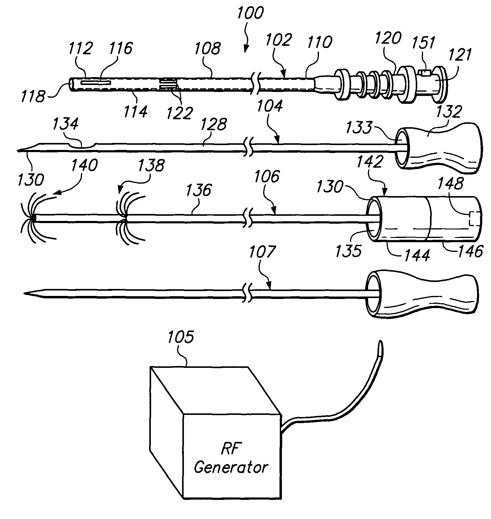
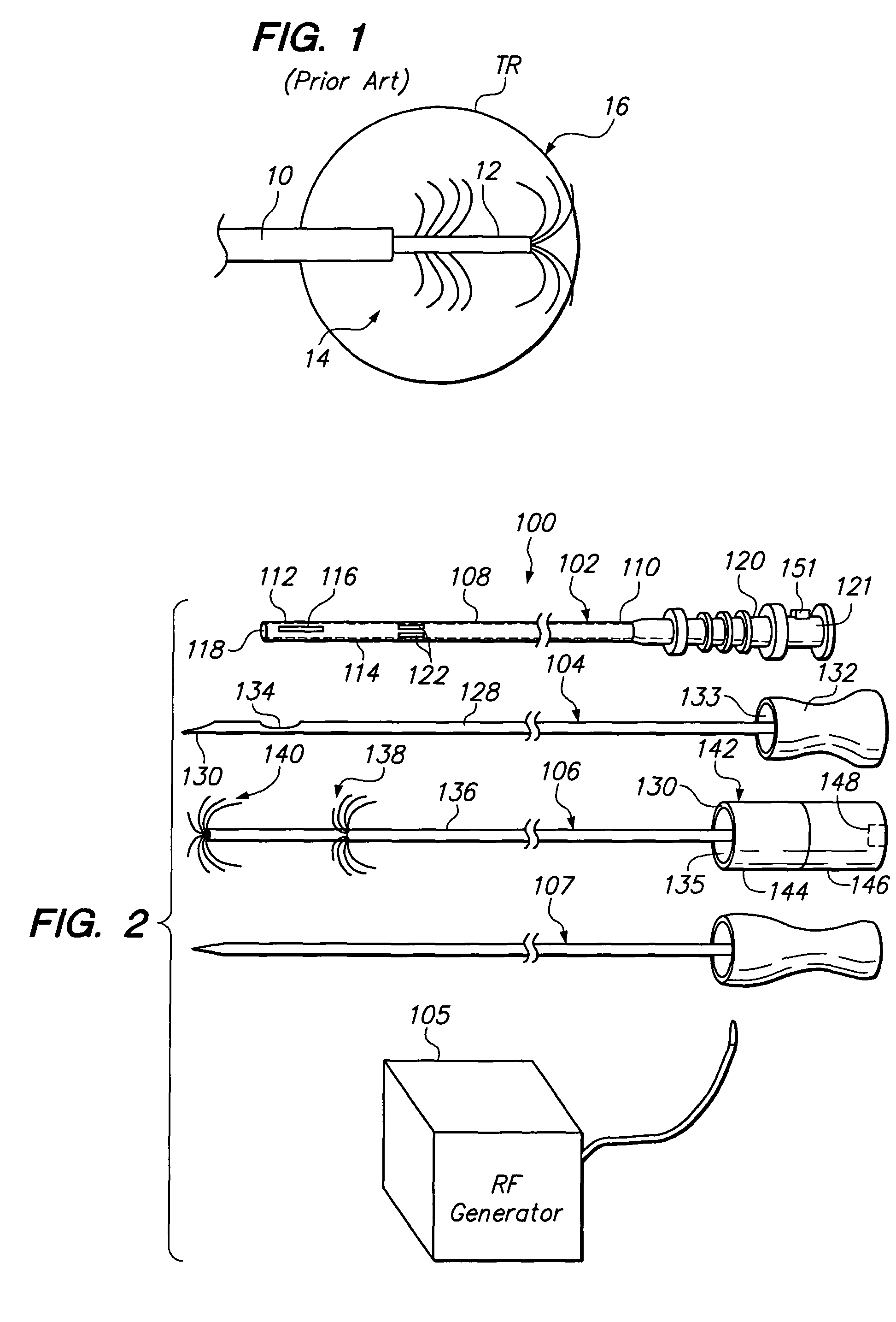
[0031]FIG. 2 illustrates a tissue treatment kit 100 arranged in accordance with a preferred embodiment of the present invention. The tissue treatment kit 100 generally comprises a delivery cannula 102 that can be percutaneously introduced within a patient, a biopsy stylet 104 configured for removing a tissue sample from the patient, and an ablation probe 106 configured for therapeutically ablating tissue. The biopsy stylet 104 and ablation probe 106 are configured to be alternately introduced through the delivery cannula 102 in contact with the tissue to be treated. The tissue treatment kit 100 may optionally comprise an obturator 107 configured for facilitating the percutaneous introduction of the delivery cannula 102 into the patient's body. The tissue treatment kit 100, and in particular, the ablation probe 106, is configured to be used with an radio frequency (RF) generator 105, as will be described in further detail below.

[0032]The delivery cannula 102 comprises a cannula shaft...


PUM


Abstract

Medical probe kits and methods for treating tissue regions (e.g. tumors) are provided. The kit comprises a delivery cannula and an ablation probe. The delivery cannula comprises a shaft, a lumen extending through the shaft, and a plurality of windows formed through a wall of the shaft in communication with the cannula lumen. The ablation probe is configured to be removably disposed within the cannula lumen. The ablation probe has a shaft and proximal and distal arrays of electrodes that are deployable from the probe shaft. The electrodes of the proximal array are configured to be deployed out from the respective windows when the ablation probe is disposed within the cannula lumen. The electrodes of the distal array may be configured to be deployed out from an axial opening at the distal end of the cannula shaft when the ablation probe is disposed within the cannula lumen. The method may comprise introducing the cannula within a patient, introducing the ablation probe through the cannula, deploying the electrode arrays into contact with the tissue region, and conveying ablation energy to the ablation probe to ablate the tissue region within the electrode arrays.

Description

FIELD OF THE INVENTION[0001]The field of the invention relates generally to the structure and use of radio frequency (RF) ablation probes for the treatment of tissue.BACKGROUND OF THE INVENTION[0002]The delivery of radio frequency (RF) energy to target regions within solid tissue is known for a variety of purposes of particular interest to the present invention. In one particular application, RF energy may be delivered to diseased regions (e.g., tumors) for the purpose of ablating predictable volumes of tissue with minimal patient trauma.[0003]RF ablation of tumors is currently performed using one of two core technologies. The first technology uses a single needle electrode, which when attached to a RF generator, emits RF energy from the exposed, uninsulated portion of the electrode. This energy translates into ion agitation, which is converted into heat and induces cellular death via coagulation necrosis. The second technology utilizes multiple needle electrodes, which have been de...

Claims


Application Information

Patent Timeline
Patent Type & Authority Patents(United States)
IPC IPC(8): A61B18/18
CPCA61B18/148A61B17/3421A61B18/1477A61B2018/0016A61B2018/1425A61B2018/143A61B2018/1432A61B2018/1475
Inventor MCCULLAGH, ORLASPIRIDIGLIOZZI, JOHN C.SAUVAGEAU, DAVID J.
Owner SCI MED LIFE SYST
Why Eureka
Try Eureka