
Sound damper for vehicle compressed air systems

a sound damper and compressed air technology, which is applied in the direction of combustion-air/fuel-air treatment, instruments, heat measurement, etc., can solve the problems of reducing the damping properties of the sound damper, and achieve the effect of ensuring effective conduction

Active Publication Date: 2012-07-10
WABCO EURO BVBA SPRL
View PDF72 Cites 18 Cited by
  • Summary
  • Abstract
  • Description
  • Claims
  • Application Information

AI Technical Summary

Benefits of technology

[0005]Generally speaking, it is an object of the present invention to provide a sound damper that ensures effective conduction of the airstream through the insulator of the sound damper.
[0014]Preferably, the knitted roll and the web are arranged so as to run parallel to one another. This makes it easier to arrange the web and knitted roll, in particular to carry out mounting, since the web can press one or more rings of the knitted roll away or together. Preferably, all the webs run parallel in this way. It is also preferred that the web, the housing and the knitted roll are arranged along a common axis of symmetry, the web and housing being designed to be radially symmetrical. This makes it possible to have a highly compact form of the sound damper.
[0015]Preferably, the web tapers at its end projecting into the insulator. This makes it easier to introduce the web into the insulator during mounting. However, other forms are also possible, for example a rounded, serrated, straight or wavy form.

Problems solved by technology

A disadvantage of known sound dampers of this type is that there is the possibility that at least part of the airstream flows past the insulator or flows under it, with the result that the damping properties of the sound damper are reduced.

Method used


Image

  • Sound damper for vehicle compressed air systems
  • Sound damper for vehicle compressed air systems

Examples


Embodiment Construction

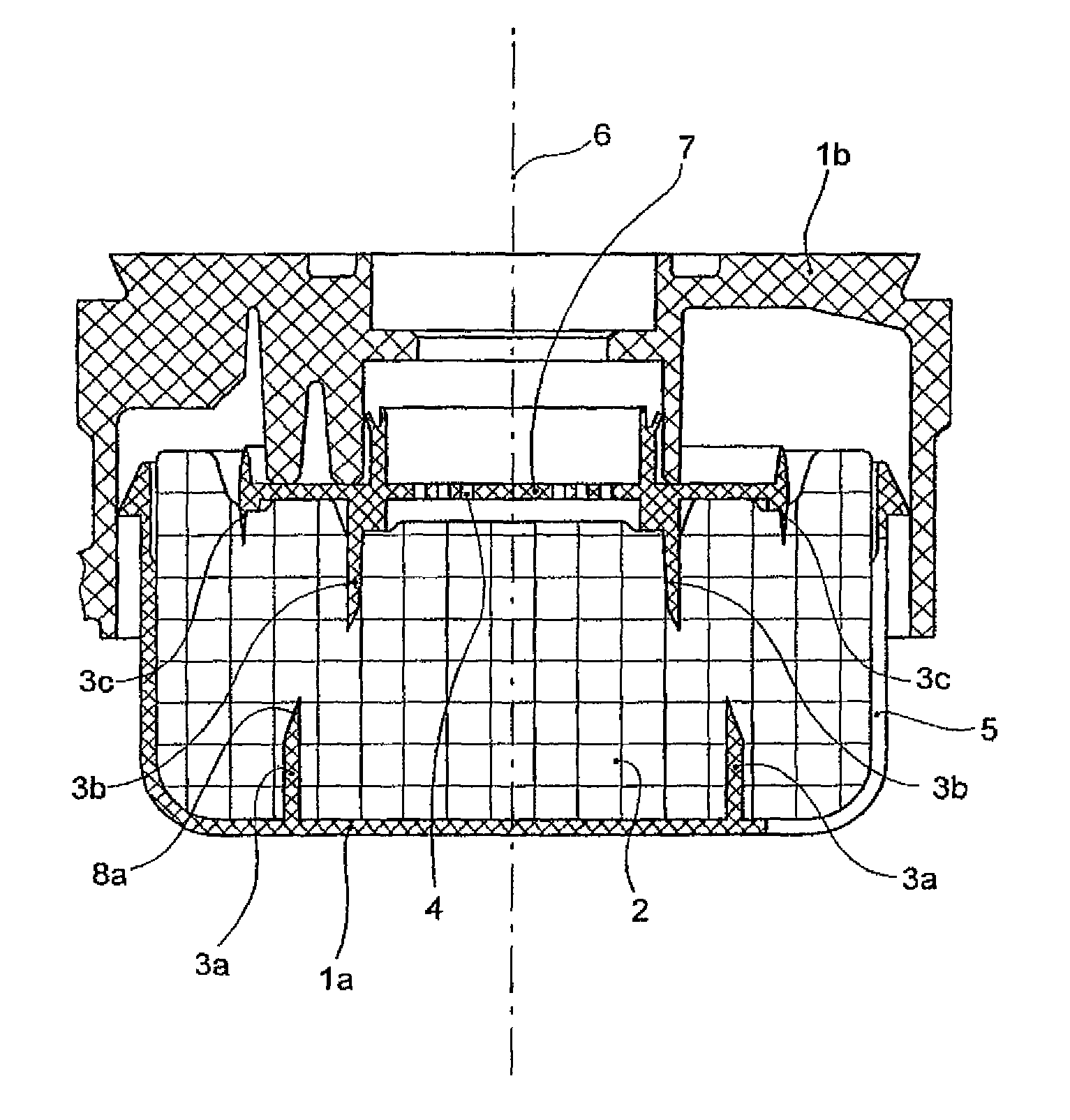
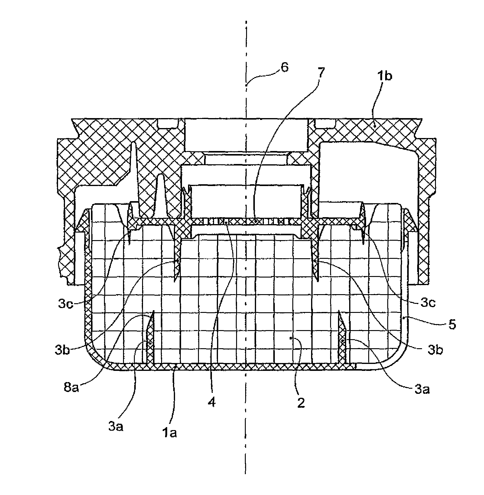
[0024]FIG. 1 shows a partially cut away sound damper according to an exemplary embodiment of the invention for compressed air systems of vehicles. In this case, the sound damper is arranged in the venting of the compressed air system in order to damp the venting noise when the compressed air system is being vented.

[0025]The sound damper comprises a housing, an insulator 2 and three webs 3a, 3b, 3c. The housing is constructed in two parts from a cover 1a and a bottom 1b. Located in the bottom 1b is an air inlet 4 and in the cover 1a an air outlet 5.

[0026]The insulator 2 is arranged inside the housing 1a, 1b. The three webs 3a, 3b, 3c are arranged inside the housing 1a, 1b such that they project into the insulator, and air flowing from the air inlet to the air outlet through the housing 1a, 1b is conducted into the insulator by the webs 3a, 3b, 3c.

[0027]The webs 3a, 3b, 3c are formed in one piece with the housing 1a, 1b. Here, the web 3a is formed in one part with the cover 1a and th...


PUM


Abstract

A sound damper for compressed air systems of vehicles includes a housing, an insulator and at least one web. The housing has an air inlet and an air outlet. The insulator is located in the housing, and the web is located in the housing such that it protrudes at least partially into the insulator. Air that flows through the housing from the air inlet to the air outlet is conducted by the web into the insulator.

Description

FIELD OF THE INVENTION[0001]The present invention generally relates to embodiments of a sound damper for a vehicle compressed air system that includes a housing and an insulator arranged inside the housing.BACKGROUND OF THE INVENTION[0002]Sound dampers of the general type under consideration are suitable particularly for use in venting the vehicle compressed air system to damp the noises generated when the compressed air system is being vented.[0003]Sound dampers of this general type are disclosed, for example, in DE 102 48 183 A1 and DE 20 2004 011 630 U1.[0004]A disadvantage of known sound dampers of this type is that there is the possibility that at least part of the airstream flows past the insulator or flows under it, with the result that the damping properties of the sound damper are reduced.SUMMARY OF THE INVENTION[0005]Generally speaking, it is an object of the present invention to provide a sound damper that ensures effective conduction of the airstream through the insulato...

Claims


Application Information

Patent Timeline
Patent Type & Authority Patents(United States)
IPC IPC(8): F02M35/00
CPCB60T17/008
Inventor HARTING, HENDRIKKONIG, HEINZ-WERNERMULLER, THOMASRIEDIGER-JANISCH, KARL-HEINZ
Owner WABCO EURO BVBA SPRL
Learn More