Mobilizer for exercise, rehabilitation and wellness

a technology for rehabilitation and wellness, applied in the field of mobility devices for exercise, rehabilitation and wellness, can solve the problems of inability to adapt to the nature or severity of a user's disability, condition or injury, and the inability of prior art walkers, canes or crutches, to readily increase or decrease depending on the severity of the disability, and achieve the effect of facilitating movement and ameliorating various mobility impairing conditions

Inactive Publication Date: 2012-07-10
THE DASHAWAY
View PDF16 Cites 35 Cited by
  • Summary
  • Abstract
  • Description
  • Claims
  • Application Information

AI Technical Summary

Benefits of technology

[0008]The present invention is a significantly improved mobility device for allowed injured, handicapped and elderly persons to move about more readily while actually aiding in rehabilitation and amelioration of various mobility impairing conditions. The inventors have coined the term “mobilizer” to distinguish their invention from previous devices.
[0009]The mobilizer consists of an open frame constructed from metallic tubes for lightness and strength. The frame is formed from two side assemblies or side frame components that are each conceptually squares (roughly 11″ or 28 cm on each side) formed from the tubing. The tubing forming the rear vertical side of the square is open top and bottom. These side assemblies are joined across the front by two elongate members. An upper elongated member connects the upper front corners of the square assemblies while a lower elongated member connects the lower front corners of the square assemblies to create a frame that resembles an inverted “U” when view from above with the legs or the “U” pointed towards the rear. The entire frame is about 22″ (56 cm) wide. Pivoting caster wheels are attached to the front lower corners of the frame lifting the bottom edge of the frame several inches above the ground. Rear wheel support arms extend rearward from the rear vertical sides of the square assemblies. These extending arms curve downward so that their distal ends can each bear a wheel that is fixedly aligned with the long axis of the support arms. These rear wheels are preferably only 60% or so the diameter of the front caster wheels. The rear wheel support arms significantly extend the rearward legs of the inverted “U” shaped frame.
[0010]Thus the mobilizer has caster wheels at the front two corners and smaller fixed wheels at the rear corners. This allows the device to be extremely maneuverable so that it can readily navigate sharp turns. The entire frame is relatively low to the ground (less than about 24″ (61 cm) high) so that the center of gravity is also very low. The distance from the axle of a front wheel to the axle of the corresponding (that is, on the same side) wheel is about 22″ (56 cm) so that the “U” formed by the frame and rear wheel support arms is essentially a square open in the rear. It will be appreciated that such a configuration is extremely stable and very resistant to tipping. For storage purposes a mechanism is provided so that the rear wheel support arms can be folded laterally to lie within the square portion of the frame.

Problems solved by technology

Disabled, injured or elderly persons often have limited mobility on their own, and need some form of support when walking or moving about.
While these prior art devices can provide adequate mobility support for many a disabled, injured, or elderly user, they fail to adapt to the nature or severity of a user's disability, condition, or injury.
Specifically, the support provided by prior art walkers, canes or crutches cannot readily be increased or decreased depending on the needs of a user.
Further, the area of the user's body supported by these devices cannot be changed.
For example, if a user needing minimal walking support injures his wrist, he would not be able to use a device providing support by way of the hands.
However, such devices may provide more support than the user requires.

Method used


Image

  • Mobilizer for exercise, rehabilitation and wellness
  • Mobilizer for exercise, rehabilitation and wellness
  • Mobilizer for exercise, rehabilitation and wellness

Examples


Embodiment Construction

[0037]The following description is provided to enable any person skilled in the art to make and use the invention and sets forth the best modes contemplated by the inventor of carrying out this invention. Various modifications, however, will remain readily apparent to those skilled in the art, since the general principles of the present invention have been defined herein specifically to provide a mobilizer to aid in walking, rehabilitation and support of disabled persons.

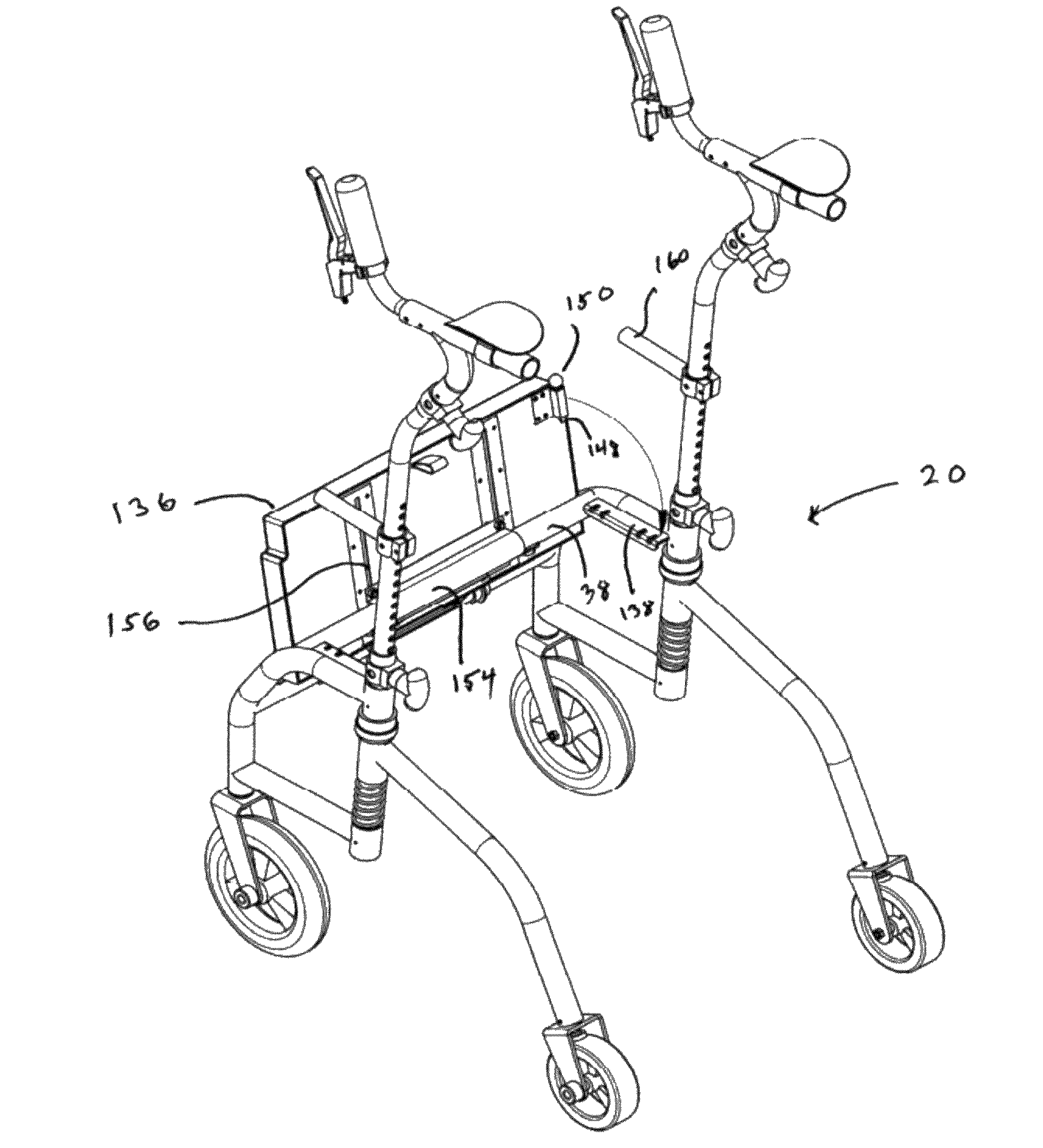
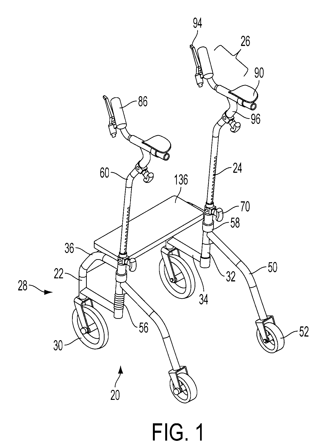
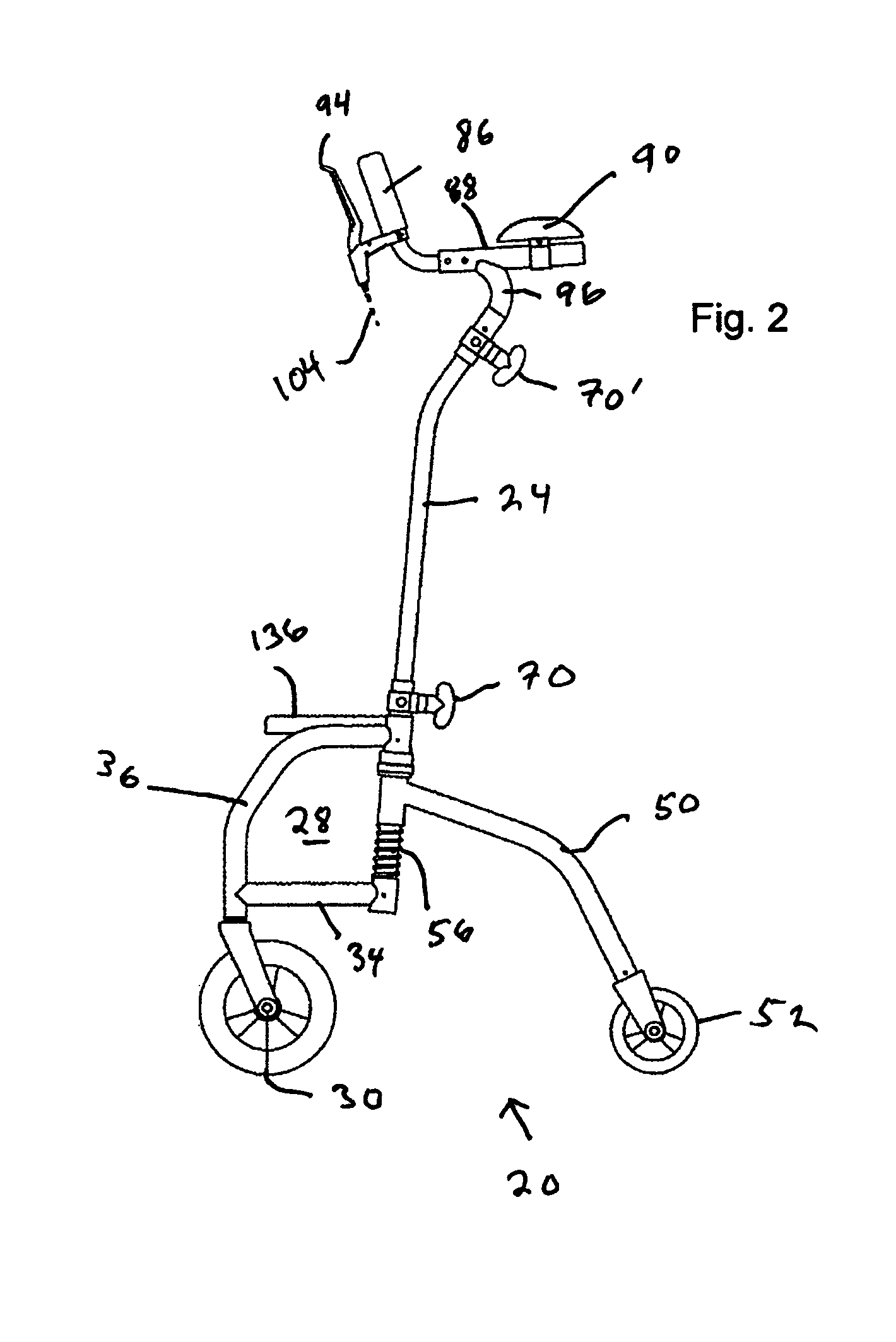
[0038]FIG. 1 shows a preferred embodiment of the mobilizer in perspective view from the rear. FIG. 2 shows a side view of the device. The device 20 is constructed as a base frame 22 and substantially upright support members 24 which bear arm support assemblies 26 for supporting the user's weight through the user's arms. Although round tubular aluminum is the presently preferred structural material, the structural members / elements of the mobilizer can be constructed from other appropriate metals such as steel, titani...


PUM


Abstract

The mobilizer consists of an open, inverted “U” shaped frame when view from above with the legs or the “U” pointed towards the rear. Pivoting caster wheels are attached to the front lower corners and rear wheel support arms extend rearward and curve downward each bearing a smaller non-pivoting wheel. Two vertical upright support members rise from the frame and are equipped with height adjustment mechanisms. Horizontal arm support assemblies, each with a hand grip and brake handle are attached to the upper ends of the support members. The user is supported by his elbows and shoulder girdle resulting in decompression of his spine. The arm support assemblies can be pivoted 180 degrees so that the grip portions and the hand brake levers face the rear of the mobilizer at about waist height. This allows the user to stand and grasp the handles as he walks forward.

Description

CROSS-REFERENCE TO PRIOR APPLICATIONS[0001]The present application is a continuation-in-part application of and claims the priority and benefit of PCT / US2007 / 078680 filed on 17 Sep. 2007 and designating the United States, which application was in turn based on, and claimed the priority and benefit, U.S. Provisional Patent Application No. 60 / 825,895 filed 15 Sep. 2006, all of which applications are incorporated herein by reference.U.S. GOVERNMENT SUPPORT[0002]Not ApplicableBACKGROUND OF THE INVENTION[0003]1. Area of the Art[0004]The present invention is directed towards a device for improving the mobility of disabled persons.[0005]2. Description of the Background Art[0006]Disabled, injured or elderly persons often have limited mobility on their own, and need some form of support when walking or moving about. Mobility support devices are well known in the art, and provide varying degrees of support depending on the needs of a user. For instance, a cane or walker may provide minimal su...

Claims


Application Information

Patent Timeline
Patent Type & Authority Patents(United States)
IPC IPC(8): B62M1/00
CPCA61H3/04A61H2003/006A61H2003/046A61H2201/0161A61H2201/1633
Inventor DASHEW, STANLEYBLOUNT, CHARLES
Owner THE DASHAWAY
Why Eureka
Try Eureka