Digital instrument with physical resonator

a digital instrument and physical resonator technology, applied in the field of stringed musical instruments, can solve problems such as human hearing limitations, and achieve the effects of changing the sound of the soundboard, facilitating insertion and removal, and great flexibility in adjusting the acoustic qualities of the soundboard

Active Publication Date: 2012-07-10
MASSACHUSETTS INST OF TECH
View PDF23 Cites 6 Cited by
  • Summary
  • Abstract
  • Description
  • Claims
  • Application Information

AI Technical Summary

Benefits of technology

[0007]It is an advantage of this invention that, in many implementations, the resonator may be easily inserted and removed through the back side of the musical instrument (i.e, the side opposite the strings). This is desirable because the strings do not need to be moved or loosened in order to insert and remove a resonator. The ease of insertion and removal makes it practicable to replace one resonator with another.
[0008]This invention gives the user great flexibility to adjust the acoustic qualities of the soundboard. These adjustments are achieved by changing physical characteristics of the soundboard, and thus changing its sound. This physical flexibility complements the flexibility and control made possible with signal processing. For example, in various implementations of this invention, a soundboard may be adjusted with apparatus for changing the material composition, boundary conditions or bracing of the soundboard or for adding or removing mass at different locations on the soundboard. Alternately, flexibility may be achieved by removing a particular soundboard and replacing it with another soundboard with different physical features and thus different tonal qualities. In a preferred embodiment of this invention, the resonator may be easily inserted and removed, thereby facilitating the interchange of resonators.

Problems solved by technology

However, sampling with sensors located in at least three places is sufficient for most purposes, given the limitations of human hearing.

Method used


Image

  • Digital instrument with physical resonator
  • Digital instrument with physical resonator
  • Digital instrument with physical resonator

Examples


Embodiment Construction

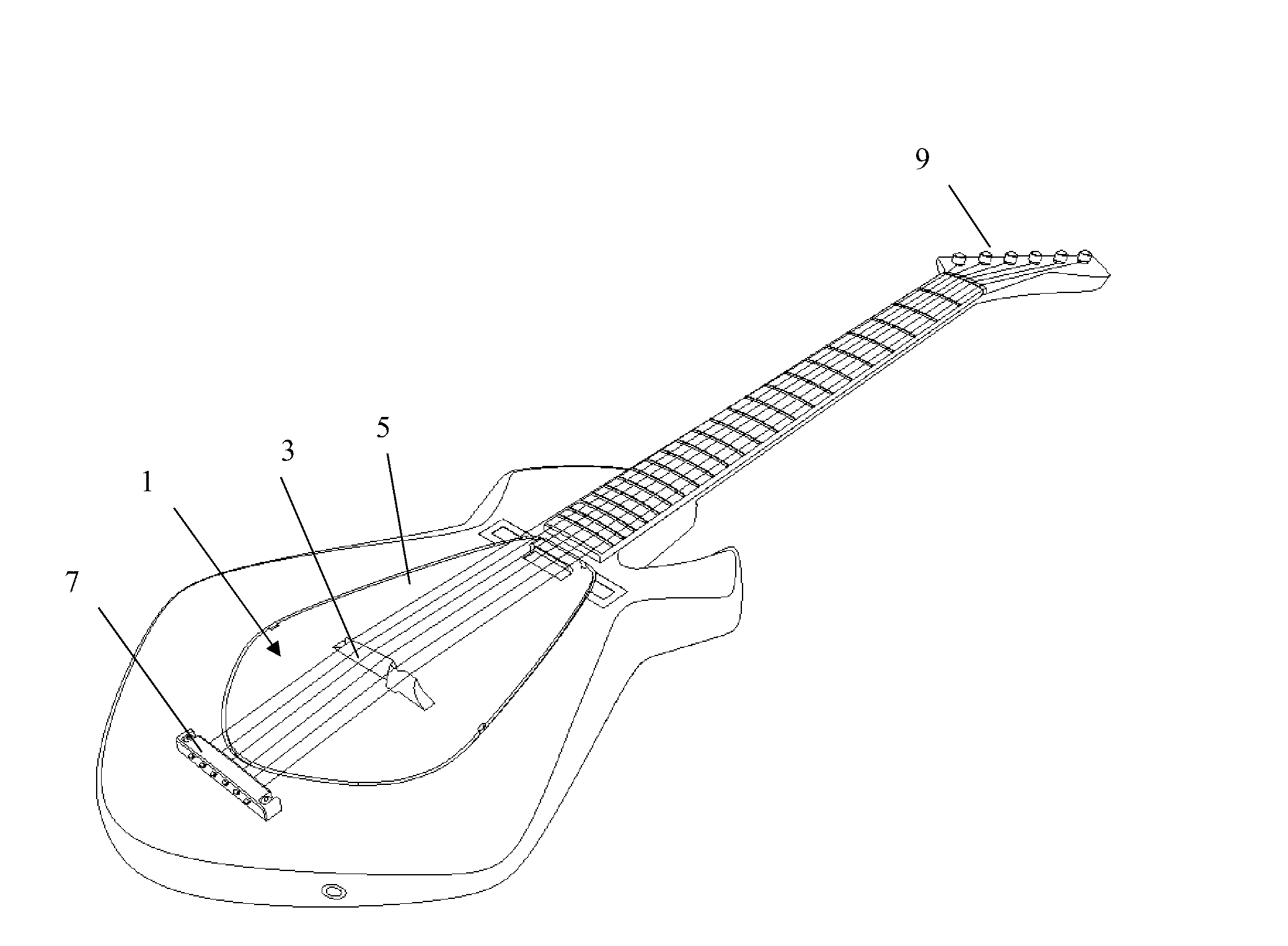
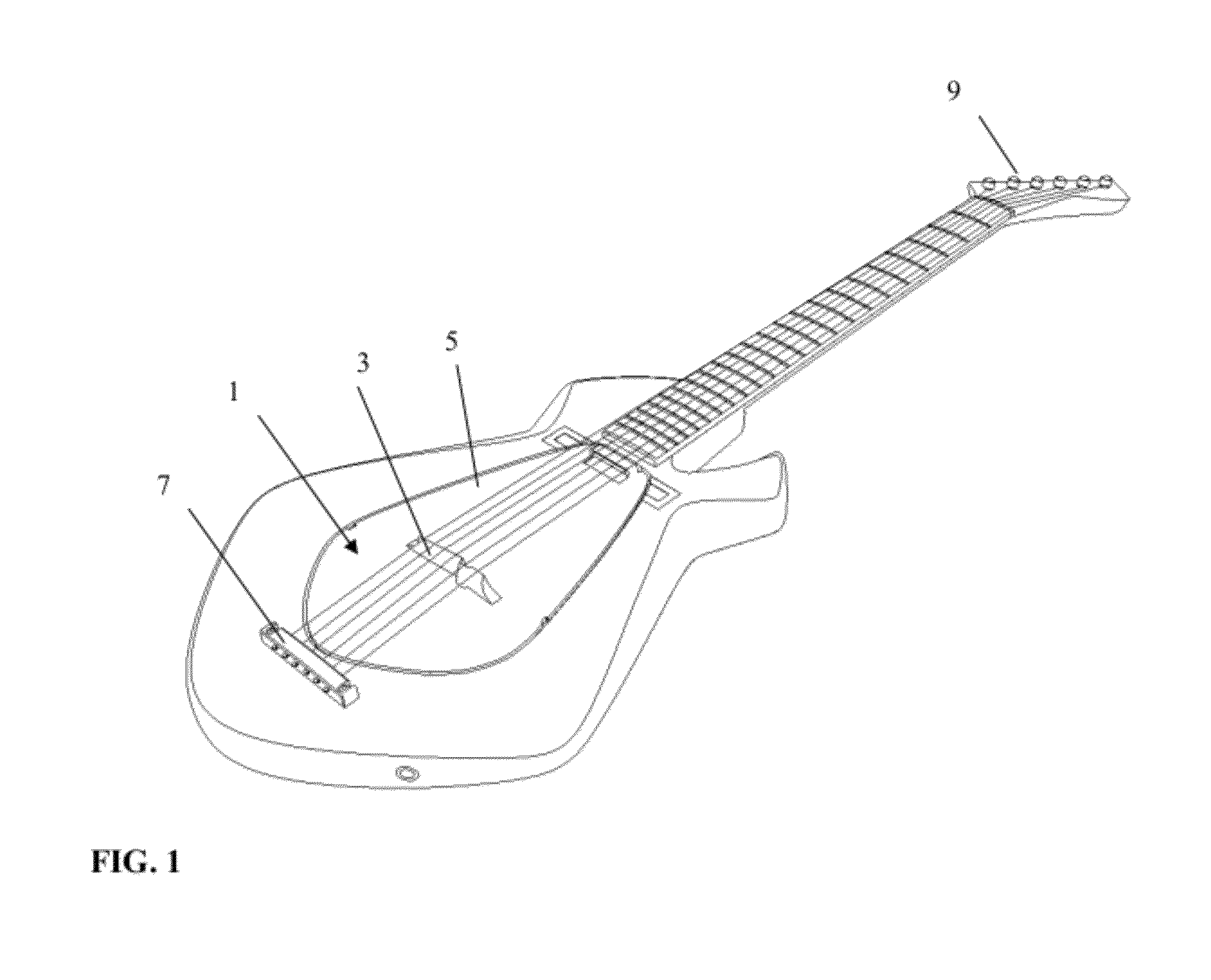
[0038]Before describing this invention, it is helpful to first briefly discuss soundboards, which are also called a sounding board, belly or plate in some instruments. Examples of soundboards include the front side of an acoustic guitar, the face plate of a violin, or a sounding board beneath the strings in a grand piano. In many stringed musical instruments, the strings are not able to create a sufficiently loud sound by themselves. To increase loudness, the vibrations of the strings are transmitted through a bridge to a soundboard, causing the soundboard to vibrate. Because the soundboard has a larger surface area than the strings, it can move a larger volume of air, producing a louder sound.

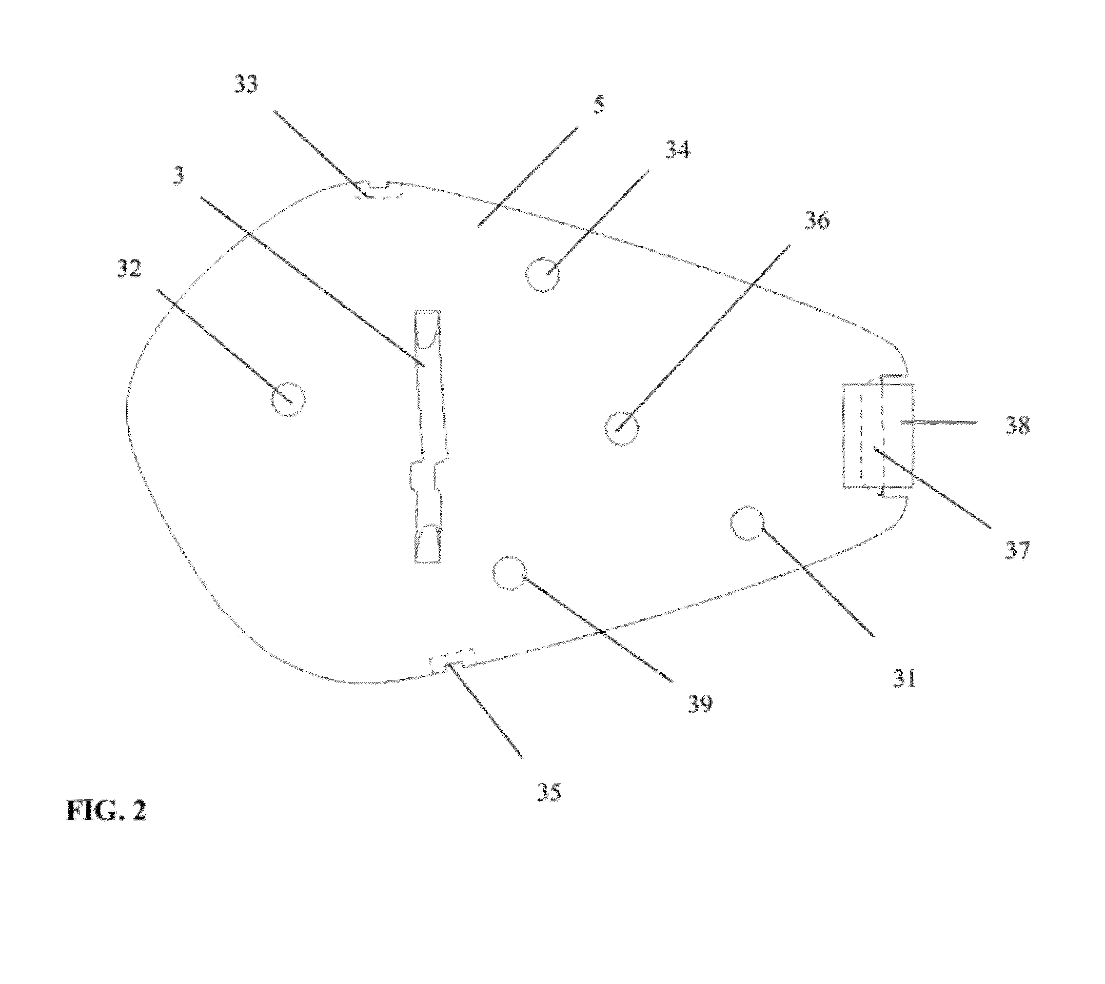
[0039]In an implementation of this invention, a stringed musical instrument has a resonator comprised of a bridge and a soundboard. Vibrations of the instrument's strings are directly or indirectly transmitted through the bridge to the soundboard. A plurality of sensors are attached to or embe...


PUM


Abstract

In an implementation of this invention, a stringed musical instrument has a resonator comprised of a bridge and a soundboard. Vibrations from the strings are transmitted through the bridge to the soundboard. A plurality of sensors are attached to or embedded in the soundboard. The sensors measure primarily the vibrations of the soundboard, rather than primarily the vibrations of the strings. Preferably, three or more sensors are used. Piezoelectric sensors sample vibrations in the soundboard. The resonator includes a printed circuit board that amplifies the signal from each sensor separately. Also, a signal processing device that is “onboard” the musical instrument processes the separate input signals to create one output signal. The resonator may be easily removed, enabling resonators to be interchanged. Also, the physical characteristics of a particular resonator, such as its mass or its boundary condition, may be adjusted, thereby changing the acoustic qualities of the soundboard.

Description

FIELD OF THE INVENTION[0001]This invention relates to stringed musical instruments.SUMMARY OF THE INVENTION[0002]In an implementation of this invention, a stringed musical instrument has a resonator comprised of a bridge and a soundboard. Vibrations from the instrument's strings are transmitted through the bridge to the soundboard. Sensors are attached to or embedded in the soundboard, and detect vibrations of the soundboard.[0003]It is highly desirable for the sensors to measure primarily the vibrations of the soundboard, as opposed to primarily the vibrations of the strings. The acoustic signal created by a vibrating soundboard is different from, and in many cases has a richer timbre than, an acoustic signal produced by vibrating strings. For example, a vibrating wooden soundboard creates a richer tone than vibrating stings alone. Moreover, because a vibrating acoustic soundboard is typically louder than the strings that cause it to vibrate, the characteristic sound of an acoustic...

Claims


Application Information

Patent Timeline
Patent Type & Authority Patents(United States)
IPC IPC(8): G10H1/32
CPCG10D1/085
Inventor ZORAN, AMIT SHLOMOCOPPIARDI, MARCO LUIGI
Owner MASSACHUSETTS INST OF TECH
Why Eureka
Try Eureka