Plug device for a container and container provided with one such device

a technology for plugging devices and containers, which is applied in the direction of packaging goods, caps, packaging foodstuffs, etc., can solve the problems of contamination risk, contamination risk, and the content of the vial being contaminated, so as to achieve the effect of convenient placemen

Active Publication Date: 2012-07-24
WEST PHARMA SERVICES DEUT GMBH & CO KG
View PDF15 Cites 44 Cited by
  • Summary
  • Abstract
  • Description
  • Claims
  • Application Information

AI Technical Summary

Benefits of technology

[0007]The present invention seeks more particularly to remedy those drawbacks by providing a novel closure device that is particularly easy to ...

Problems solved by technology

When the metal capsule is crimped onto the top portion of a glass vial, it is possible for particles of glass to become detached from the vial, which particles can drop onto the top of the stopper and constitute a risk of polluting the content.
During this time interval, it is th...

Method used


Image

  • Plug device for a container and container provided with one such device
  • Plug device for a container and container provided with one such device
  • Plug device for a container and container provided with one such device

Examples


second embodiment

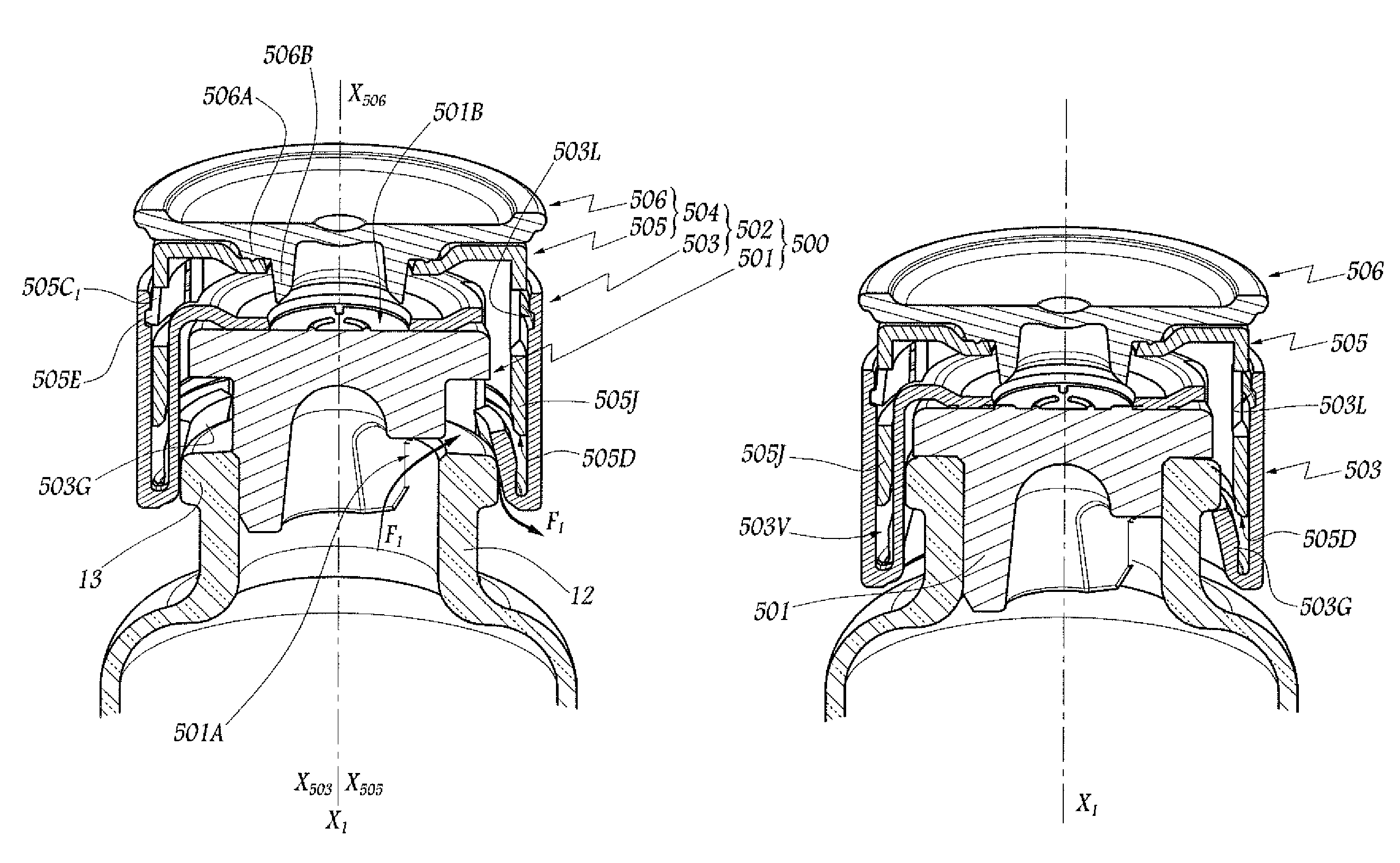
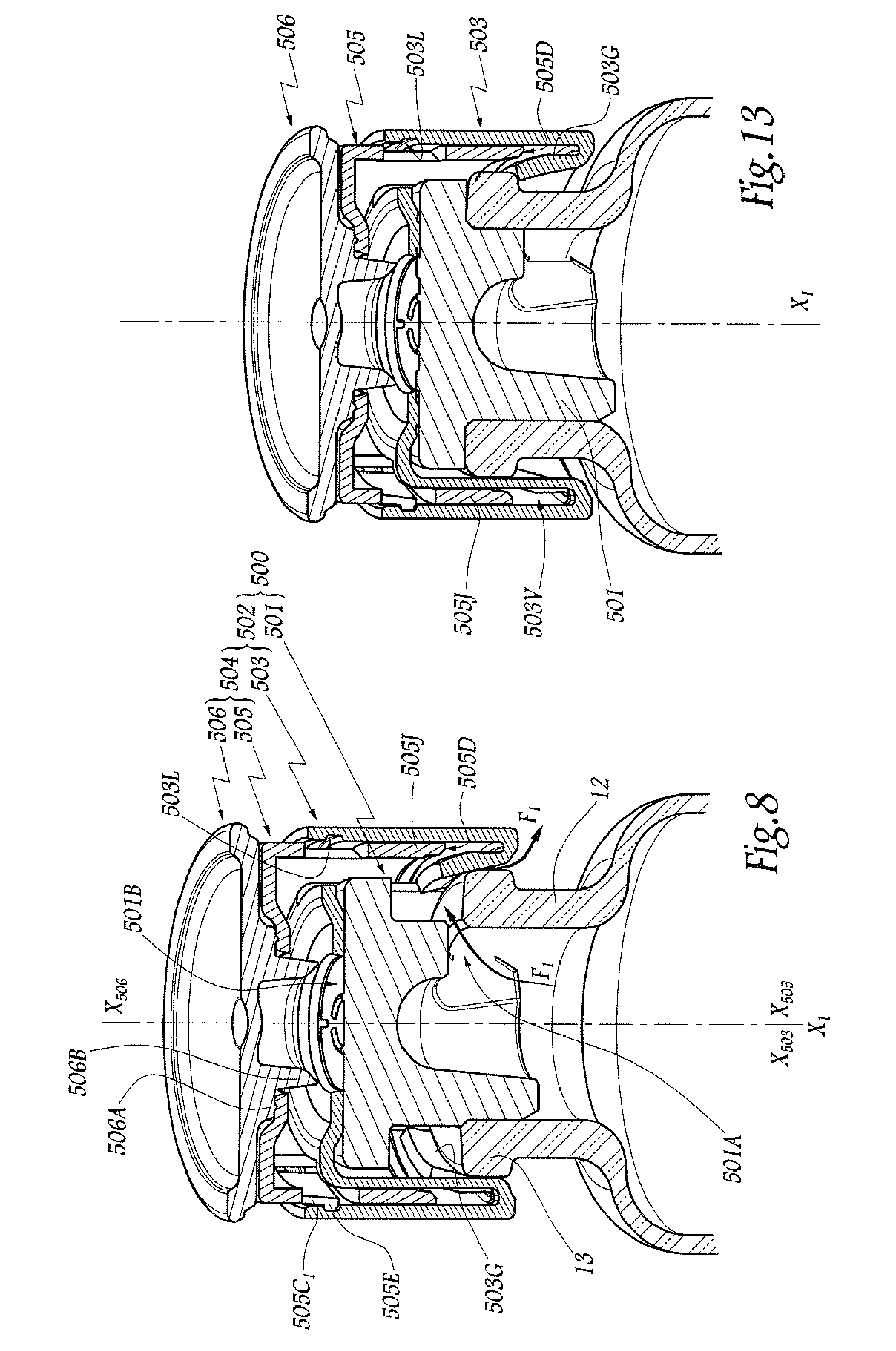
[0069]In the second embodiment shown in FIG. 16, elements analogous to those of the above embodiment are given identical references. The cover 502 of this embodiment likewise comprises a ring 503 and a drive member 504 formed by a key 505 and a cap 506. This embodiment differs from the above embodiment in that the four tongues 505C of the key 505 are all of the same type and they extend to the same distance d1 from the annular edge 505D of the skirt 505J. These four tongues 505C have the same function as the tongues 505C1 in the above embodiment and they come simultaneously into engagement in a groove 503L formed in the inside of the ring 503 that is identical to the ring in the above embodiment.

[0070]The annular portion 505A of the key 505 is provided with six hooks, only two of which can be seen in FIG. 16 under the reference 505F beside the opening 505B adjacent to the portion 505A facing towards the edge 505D. These six hooks 505F are designed to engage with the edge 503P of the...

first embodiment

[0079]The ring 503 is identical to that of the

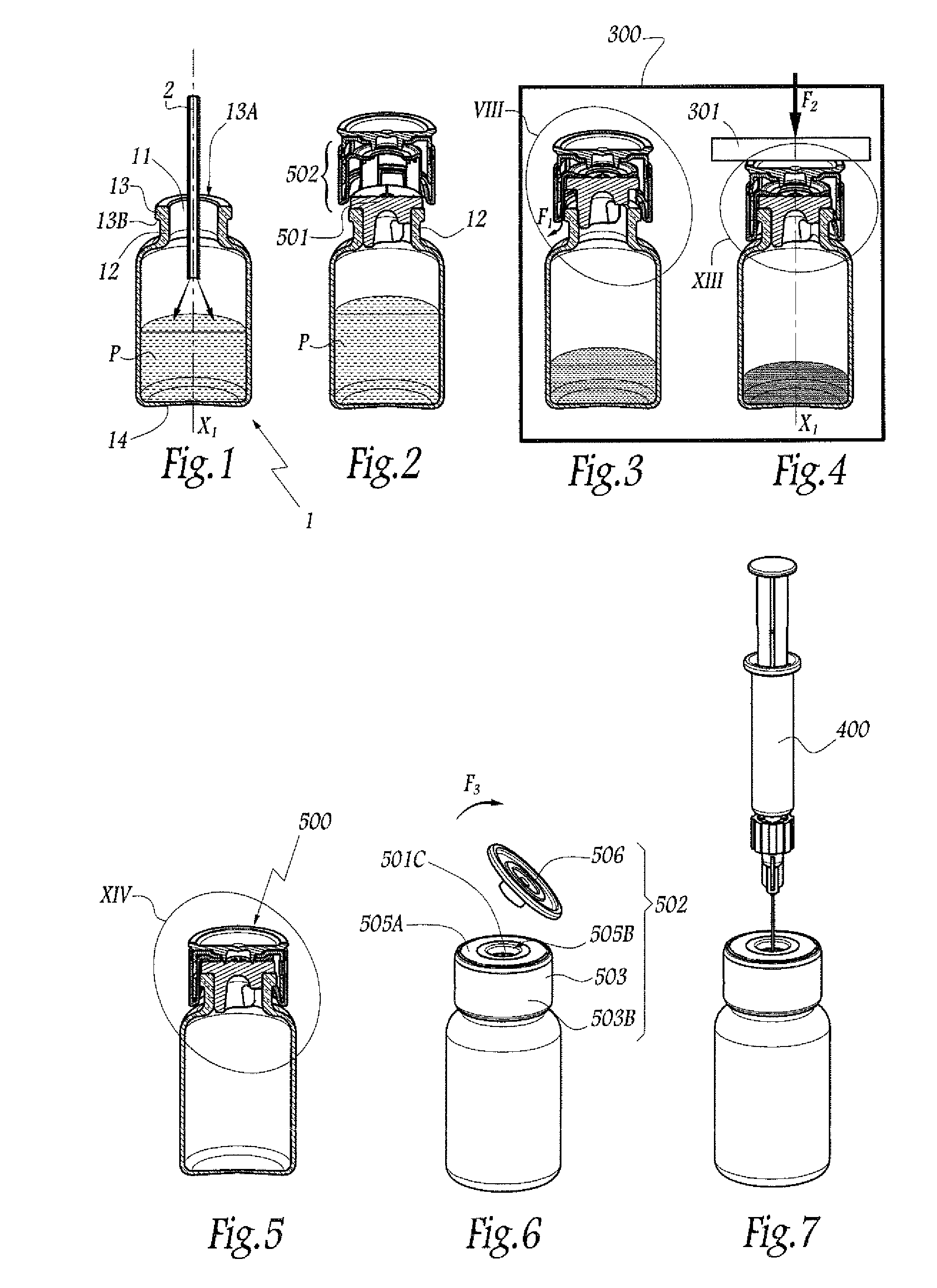
[0080]When the cap 506 is to be mounted on the key 505, it is necessary to engage the catches 506A1 against the edge 505B1 through the opening 505B. To do this, as shown in FIG. 25, the key 505 is placed on a tool 600 that defines an annular surface 601 for receiving the portion 505A of the key 505 bearing thereagainst. The stopper 506 is then presented above the key 505, with the axes X505 and X506 substantially in alignment, the axis X506 already being in alignment on a central axis X600 of the tool 600. The cap 506 is then pushed towards the tool 600 with a force F0 parallel to the axes X505, X506, and X600, thereby having the effect of engaging the lip 506B in the opening 505B and then causing the catches 506A1 to bear against the edge 505B1 of the opening 505B. When the force F0 is maintained on the cap 506, the surface 506C comes to bear against the top surface 505A1 of the portion 505A and transmits a force F′0 to the key 505, the...


PUM

PropertyMeasurementUnit
Fractionaaaaaaaaaa
Forceaaaaaaaaaa
Volumeaaaaaaaaaa

Abstract

The closure device (500) comprises a stopper (501) made of elastomer and a cover (502) suitable for covering both the neck (12) of a container and stopper (501) in place in said neck (12). The cover (502) is made of plastics material and comprises a ring (503) and a drive member (504). The ring (503) may surround the stopper (501) and the neck (12) in the mounted configuration, the ring being provided with locking means (503G) for locking on the neck (12). The drive member (504) may be mounted on the ring (503) in arbitrary angular orientation about a central axis (X503) of the ring. The drive member is provided with an annular edge (505D) suitable for being engaged between an outer skirt (503A) of the ring (503) and at least one tab (503G) forming locking means and extending radially towards the central axis (X503) of the ring from the skirt (503A).

Description

BACKGROUND OF THE INVENTION[0001]1. Field of the Invention[0002]The invention relates to a closure device for a container having a neck, and also to a method of mounting such a device, and to a container fitted with such a device.[0003]2. Description of the Related Art[0004]In the field of containers for medication, it is known to use a glass vial for conserving an active principle in the form of a freeze-dried lyophilisate, a powders, or a liquid solution. Such a vial needs to be closed in sealed manner so as to keep its content in a satisfactory state of conservation until the time it is used. In order to close a vial hermetically, it is known to use a closure device that comprises an elastomer stopper having the function of being completely leaktight against gas, liquids and bacteria, a capsule made of metal, usually aluminum, that provides a sealing function, and a “flip-off” tongue that performs a tamperproofing indicator function and that needs to be removed before it is possi...

Claims


Application Information

Patent Timeline
IPC IPC(8): B65D51/00
CPCB65D51/002B65D51/241A61J1/1406Y10S604/905Y10T29/53
Inventor ANEAS, ANTOINE
Owner WEST PHARMA SERVICES DEUT GMBH & CO KG
Why Eureka
Try Eureka