Broadband patch antenna and antenna system

a patch antenna and antenna technology, applied in the direction of antenna earthing, substantially flat resonant elements, resonance antennas, etc., can solve the problems of difficult off-board connection to patch antennas, narrow bandwidth of patch antennas, and difficulty in achieving wideband patch antennas. , to achieve the effect of increasing bandwidth, and reducing the number of antennas

Active Publication Date: 2012-07-31
NORTHROP GRUMMAN SYST CORP
View PDF24 Cites 63 Cited by
  • Summary
  • Abstract
  • Description
  • Claims
  • Application Information

AI Technical Summary

Benefits of technology

[0009]Embodiments of the present invention comprise patch antennas with increased bandwidth and patch antennas that include efficient connection arrangements to other electrical elements in an antenna system, while still providing the size and durability advantages of a substrate-based system.
[0010]An embodiment of the invention is a patch antenna including a dielectric substrate and a grounding conductor plane formed on a first surface of the dielectric substrate. At least one patch radiator is formed on a second surface of the dielectric substrate. Each of the patch radiators includes a feed point connected to a first edge of the patch radiator and at least one tuning slot extending from an edge of the patch radiator at least partially toward an interior section of the patch radiator. The at least one tuning slot is separate from the feed point and configured to enhance a bandwidth of the patch antenna.

Problems solved by technology

However, patch antennas generally have a relatively narrow bandwidth.
Consequently, conventional patch antennas may not be as useful in applications requiring a wider bandwidth.
These off-board connections to patch antennas can be difficult because the impedance must be carefully matched to the antenna.
However, because of the spacers, air-spaced patch antennas consume much more space and are often less rugged than substrate-based patch antennas.

Method used


Image

  • Broadband patch antenna and antenna system
  • Broadband patch antenna and antenna system
  • Broadband patch antenna and antenna system

Examples


Embodiment Construction

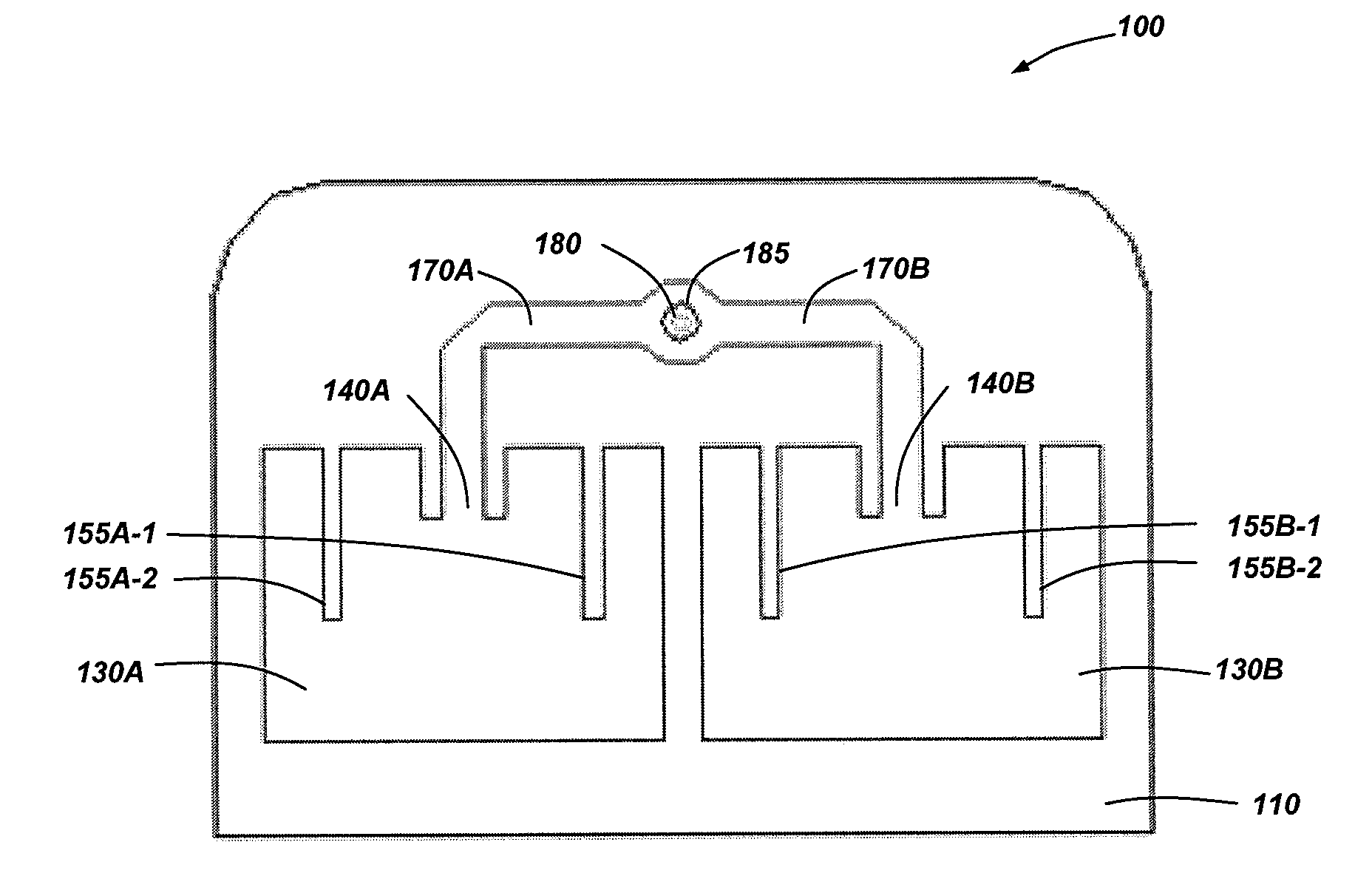
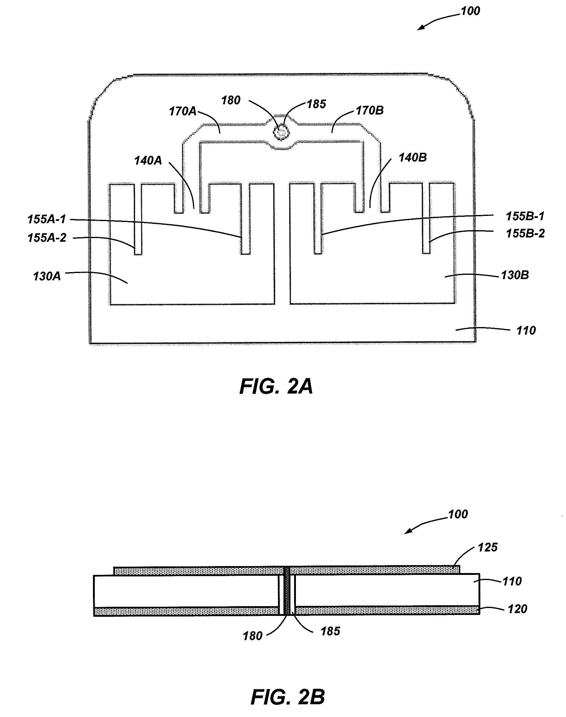
[0024]Embodiments of the present invention comprise patch antennas with increased bandwidth and patch antennas that include efficient connection arrangements to other electrical elements in an antenna system, while still providing the size and durability advantages of a substrate-based system.

[0025]In the following detailed description, reference is made to the accompanying drawings which form a part hereof, and in which is shown by way of illustration specific embodiments in which the invention may be practiced. These embodiments are described in sufficient detail to enable those of ordinary skill in the art to practice the invention. It should be understood, however, that the detailed description and the specific examples, while indicating examples of embodiments of the invention, are given by way of illustration only and not by way of limitation. From this disclosure, various substitutions, modifications, additions, rearrangements, or combinations thereof within the scope of the ...


PUM


Abstract

A patch antenna includes a ground plane on a surface of a substrate. Patch radiators are formed on another surface of the substrate. Each patch radiator includes tuning slots extending from an edge of the patch radiator toward an interior section such that the slot is separate from a feed point of the patch radiator. In some embodiments, the patch antenna includes a first feed-through conductor disposed through the ground plane and substrate and coupled to the patch radiator. In some embodiments the patch antenna with the first feed-through conductor is a razor patch antenna. An antenna system includes a patch antenna and a transceiver board, which includes a substrate and a ground plane on the substrate. A second feed-through conductor runs through the ground plane and transceiver substrate to connect to a transceiver device. The transceiver board and patch antenna are abutted such that the first and second feed-through conductors connect.

Description

CROSS-REFERENCE TO RELATED APPLICATION[0001]This application claims the benefit of U.S. Provisional Patent Application Ser. No. 61 / 055,728, filed May 23, 2008 and entitled BROADBAND PATCH ANTENNA, the disclosure of which application is incorporated by reference herein in its entirety.TECHNICAL FIELD[0002]Embodiments of the present invention relate generally to antennas and antenna systems. More specifically, embodiments of the present invention relate to microstrip patch antennas.BACKGROUND[0003]Antennas are used to receive or radiate electromagnetic energy. Generally, the antenna forms part of a communication system and the electromagnetic energy carries information in the form of a signal on a carrier signal at one or more desired frequencies.[0004]A patch antenna is one type of antenna that gets its name from the fact that is essentially a metal patch disposed over a ground plane. The ground plane and metal patch are separated by a dielectric, which may be air, foam or other suit...

Claims


Application Information

Patent Timeline
Patent Type & Authority Patents(United States)
IPC IPC(8): H01Q1/38
CPCH01Q9/0407H01Q9/0442H01Q13/10H01Q13/18H01Q23/00
Inventor BUCCA, STEVENGAWRONSKI, MIKE
Owner NORTHROP GRUMMAN SYST CORP
Why Eureka
Try Eureka