Surgical stapling device with captive anvil

a technology of stapling device and anvil, which is applied in the direction of surgical staples, surgical forceps, paper/cardboard containers, etc., can solve the problems of high force or strain on the mechanical components of the clamping mechanism of the cutting and stapling device, failure of the clamping mechanism, and misalignment between the jaws, so as to maintain the accuracy of the positioning of the staple pocket, increase the clamping force, and ensure the integrity of the anvil and the housing

Active Publication Date: 2012-08-07
TYCO HEALTHCARE GRP LP
View PDF13 Cites 1044 Cited by
  • Summary
  • Abstract
  • Description
  • Claims
  • Application Information

AI Technical Summary

Benefits of technology

[0009]Example embodiments of the present invention provide a high-strength anvil and housing while maintaining accurate anvil to staple pocket positioning. This may be accomplished by integrating the pivot point into the anvil and housing geometry rather than using a separate pivot pin. This design may be advantageous in that the integrity of the anvil and housing is not compromised by the need to drill a through hole for a pin. In this regard, a portion of material (which would otherwise be removed due to drilling of a through hole) remains in the region of the pivot point to assist in supporting the significant loads exerted during the compression of tissue. This may result in increased clamping force with less deflection in the anvil and / or the housing.
[0012]According to an example embodiment, the anvil and cartridge housing are configured so that the anvil is generally laterally confined in a particular arrangement by the cartridge housing. This is accomplished by one or more structures of the anvil being receivable in a slot or space formed in the cartridge housing. For example, two wings of the anvil may be received in two corresponding slots of the cartridge housing. This slot configuration allows the presence of the cartridge housing structure around a relatively high portion of the circumference of the cartridge housing, which may be advantageous with regard to the strength of the cartridge housing.
[0013]The slotted arrangement may also be advantageous with regard to the anvil, since the structure of the cartridge housing extends on laterally outward sides of the wings and between the wings when the anvil is mated to the cartridge housing. This may, e.g., decrease the likelihood of lateral deflection of the wings.
[0014]The anvil of the example embodiment also has a cam slot for actuation of the anvil that does not extend laterally through the anvil. This blind slot may increase the strength of the anvil due to the presence of more structure on the outer surface as opposed to a through slot.
[0020]The device may also include a secondary positioning member coupled to one of the first jaw and the second jaw and configured to prevent removal of the first jaw from the second jaw and to allow rotation of the first jaw with respect to the second jaw.
[0034]The device may further include a secondary positioning member coupled to one of the first jaw and the second jaw and configured to prevent axial removal of the first jaw from the second jaw and to permit rotation of the first jaw with respect to the second jaw.

Problems solved by technology

During this compression, the mechanical components of the clamping mechanism of the cutting and stapling device may be subjected to a high level of force or strain.
Where, e.g., the jaws are closed by rotation of one or both of the jaws about a proximally located pin, the pin and / or the adjacent structures of the jaws in communication with the pin bear a substantial load, which may lead to deformation.
This deformation may lead to, e.g., misalignment between the jaws and / or failure of the clamping mechanism.
Where one of the jaws is configured as an anvil and the other jaw is configured to drive staples, e.g., from a staple cartridge, into the anvil, misalignment of the jaws may cause misalignment of the anvil and staple pockets.
This may cause the staples to be improperly formed, which may increase the risk of sepsis and other potentially dangerous complications.
This may, e.g., decrease the likelihood of lateral deflection of the wings.

Method used


Image

  • Surgical stapling device with captive anvil
  • Surgical stapling device with captive anvil
  • Surgical stapling device with captive anvil

Examples


Embodiment Construction

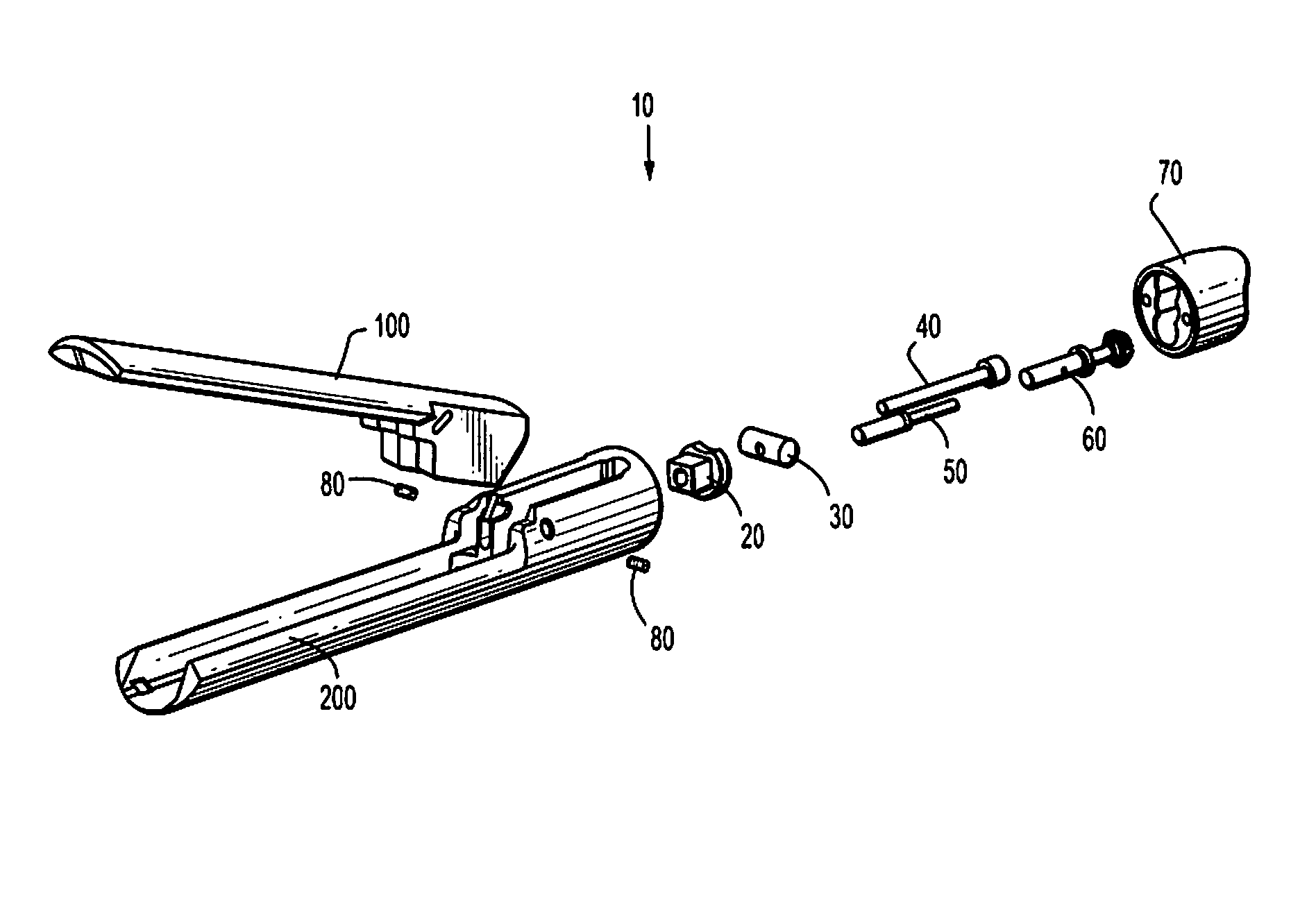
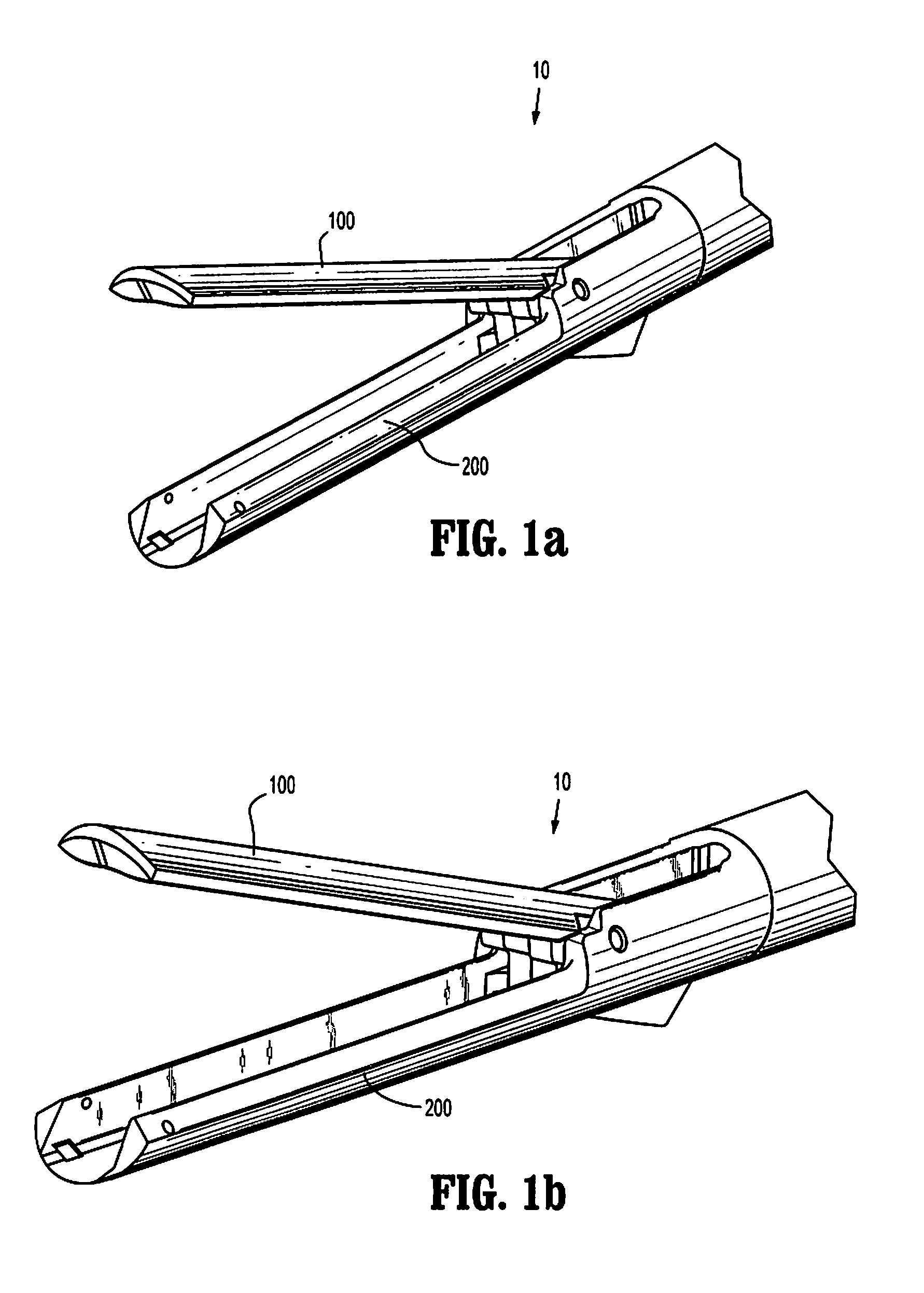
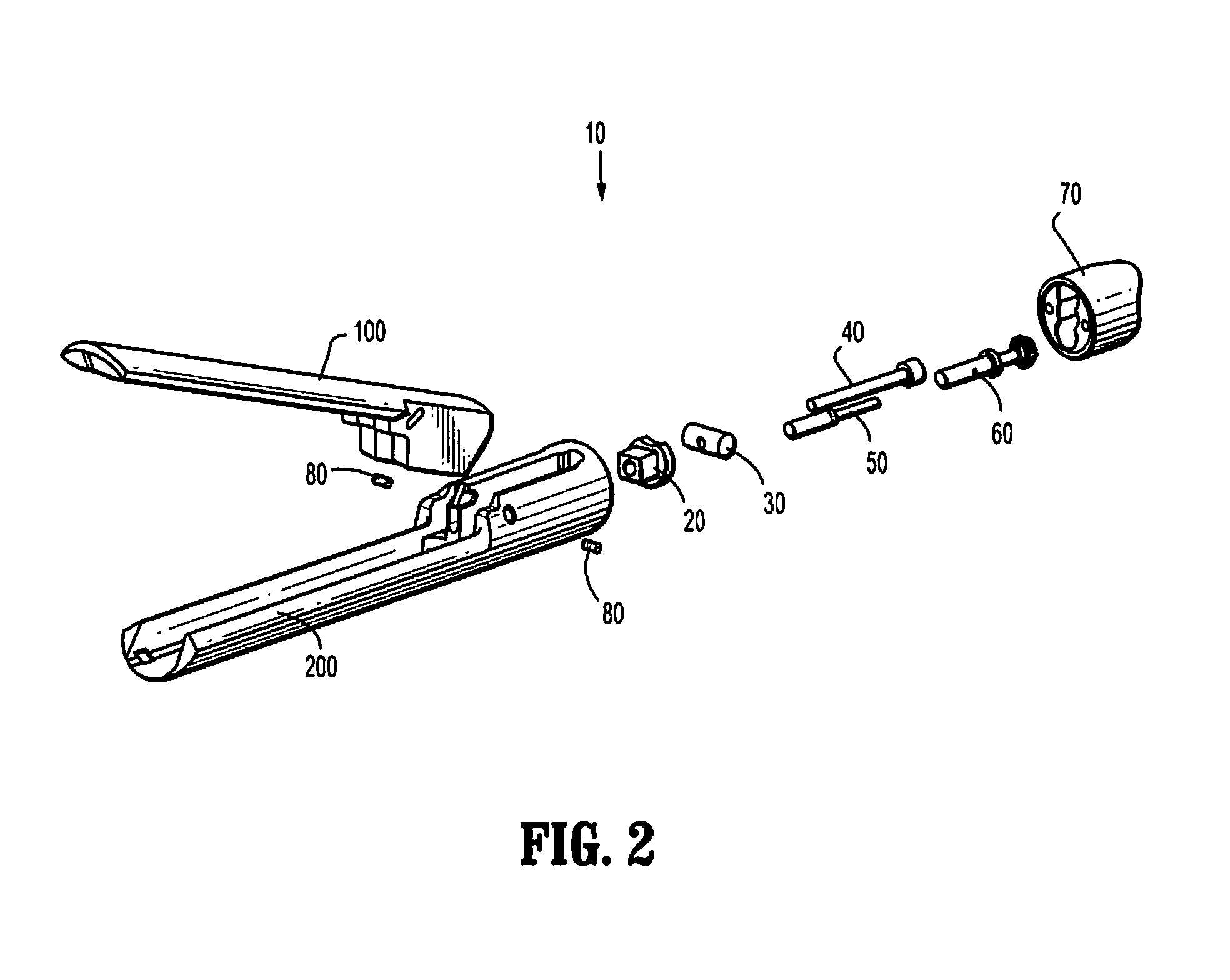
[0057]FIGS. 1a and 1b show a clamping device 10 of a linear cutting and stapling device according to an example embodiment of the present invention. The clamping device 10 includes an anvil 100 as a first jaw or clamping member, and a cartridge housing 200 as a second jaw clamping member. As shown in FIGS. 1a and 1b, the anvil 100 and the cartridge housing 200 are in an open state. The anvil 100 and cartridge housing 200 are rotatable about each other to close from the open state to a closed state where the anvil 100 and cartridge housing 200 are parallel, or substantially parallel, to maintain a tissue gap therebetween that allows for satisfactory staple formation between the cartridge housing 200 and the anvil 100.

[0058]It is noted that the clamping device 10 is symmetric, or substantially symmetric, about a plane extending through an axial centerline of the clamping device 10. Thus, although some features may be described with respect to one side of the clamping device, it should...


PUM

PropertyMeasurementUnit
clamping forceaaaaaaaaaa
rotationaaaaaaaaaa
axis of rotationaaaaaaaaaa

Abstract

A device for clamping tissue includes a first jaw having a distal portion for communicating with tissue and a proximal portion having a first wing and a second wing. The device also includes a second jaw having a distal portion for communicating with tissue and a proximal portion having a first slot and a second slot, the first slot disposed between a middle structure and a first lateral structure, the second slot disposed between the middle structure and a second lateral structure. The first jaw is rotatably coupleable to the second jaw with the first wing extending into the first slot and the second wing extending into the second slot.

Description

FIELD OF THE INVENTION[0001]The present invention relates generally to a surgical clamping device.BACKGROUND INFORMATION[0002]Some surgical procedures require the compression, e.g., clamping, of a patient's tissue. Such procedures may include, e.g., anastomosing, stapling, and resecting of tissue. For example, where cancerous tissue is identified in a patient's gastrointestinal tract, the cancerous tissue may need to be surgically removed. Where, for example, the cancerous tissue is located on the colon and is accessible by surgical instrumentation, the surgeon may make an incision in the patient's abdomen to allow access to the bowel. The surgeon may then use a linear cutting and stapling device, such as that described in U.S. Patent Application Publication No. 2009 / 0101692, which is expressly incorporated herein in its entirety by reference thereto, to cut and staple the colon tissue on opposite sides of the cancerous portion to be removed. In this procedure, the colon is external...

Claims


Application Information

Patent Timeline
Patent Type & Authority Patents(United States)
IPC IPC(8): A61B17/068
CPCA61B17/07207A61B17/068A61B17/00234A61B2017/00734A61B2017/2926A61B2017/2943A61B2017/07214
Inventor NICHOLAS, DAVID A.DATCUK, PETERWHITMAN, MICHAEL P.
Owner TYCO HEALTHCARE GRP LP
Why Eureka
Try Eureka