Electrostatic atomizer

Active Publication Date: 2012-08-07
PANASONIC CORP
View PDF12 Cites 3 Cited by
  • Summary
  • Abstract
  • Description
  • Claims
  • Application Information

AI Technical Summary

Benefits of technology

[0007]In view of the above problems of the prior art, it is an object of the present invention to provide an electrostatic atomizer which can make a physical object, such as an article stored in a mist-receiving space or an inner wall of a structural member defining the mist-receiving space, less likely to be electrostatically charged.

Problems solved by technology

This causes a problem that, if a user touches the physical object C by his / her hand, the static charges will be discharged through the hand to make his / her feel uncomfortable.[Patent Publication 1] Japanese Unexamined Patent Publication No. 2006-68711

Method used


Image

  • Electrostatic atomizer
  • Electrostatic atomizer
  • Electrostatic atomizer

Examples


first embodiment

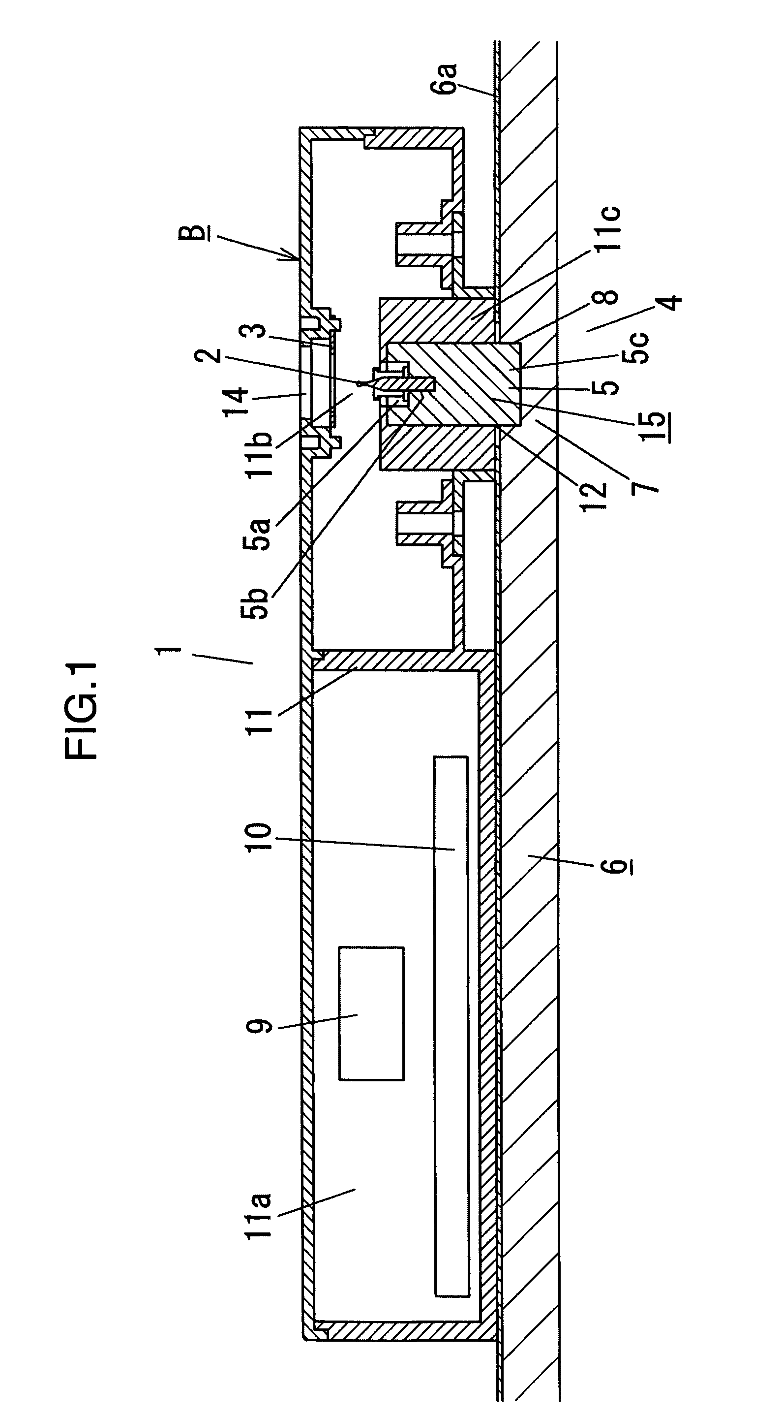
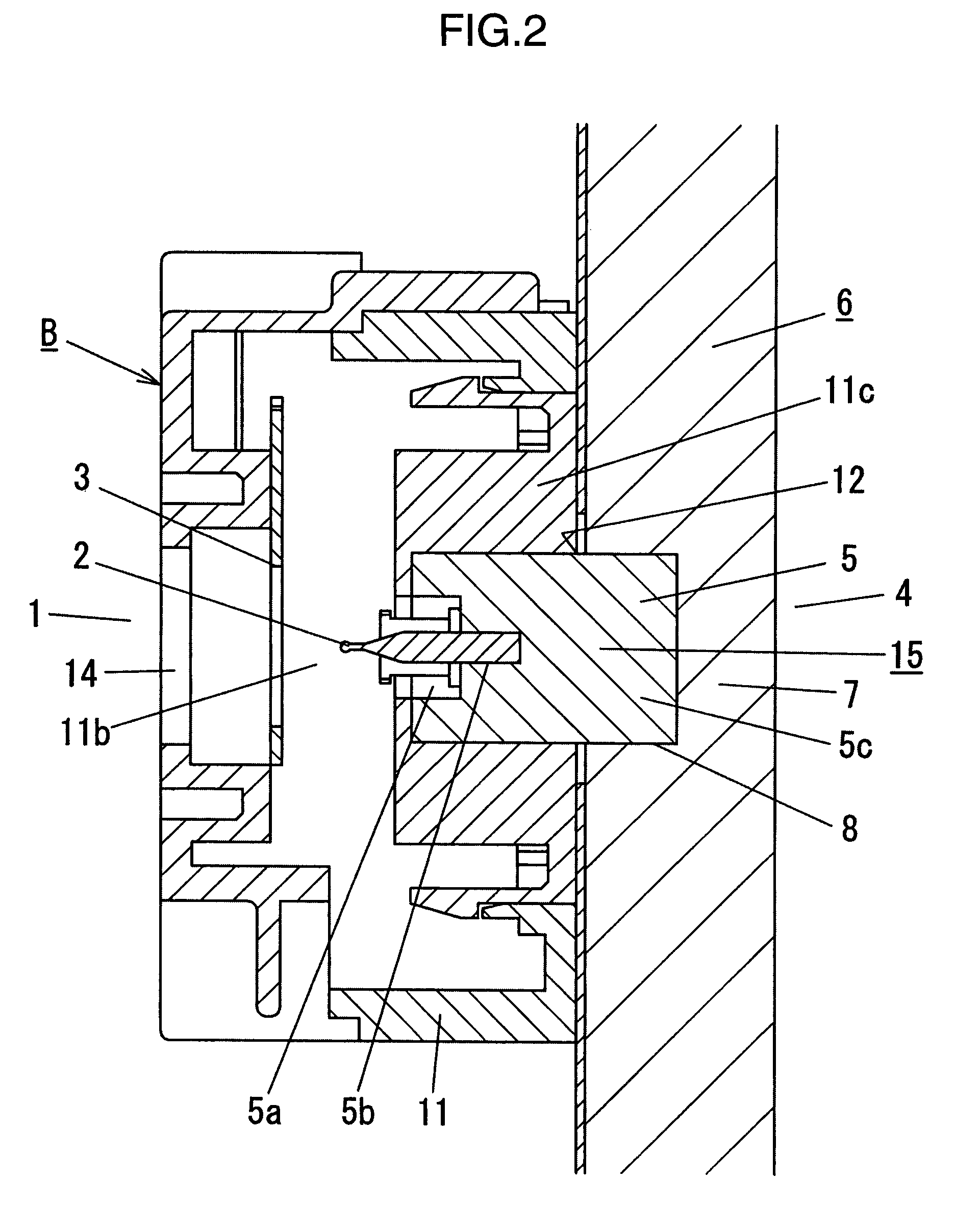
[0022]Although the first embodiment illustrated in FIGS. 1 to 3 will be described by taking a refrigerator A1 as one example of the apparatus A having the mist-receiving space 1 and the cold space 4, an apparatus suitable for applying the inventive electrostatic atomizer is not limited to the refrigerator A1.

[0023]FIG. 3 is a schematic diagram showing an internal structure of the refrigerator A1. In FIG. 3, the refrigerator A1 comprises a refrigerator housing 20 which is internally provided with a freezing compartment 21, a vegetable compartment 22, a cooling compartment 23 and a cold-air passage 24. In an outer shell of the refrigerator housing 20, each of the freezing compartment 21, the vegetable compartment 22, the cooling compartment 23 and the cold-air passage 24 is divided by a partition wall 6. The partition wall 6 is made of a heat-insulating material. Further, an outer skin 6a formed of a synthetic-resin molded product is integrally laminated on a surface of the partition ...

second embodiment

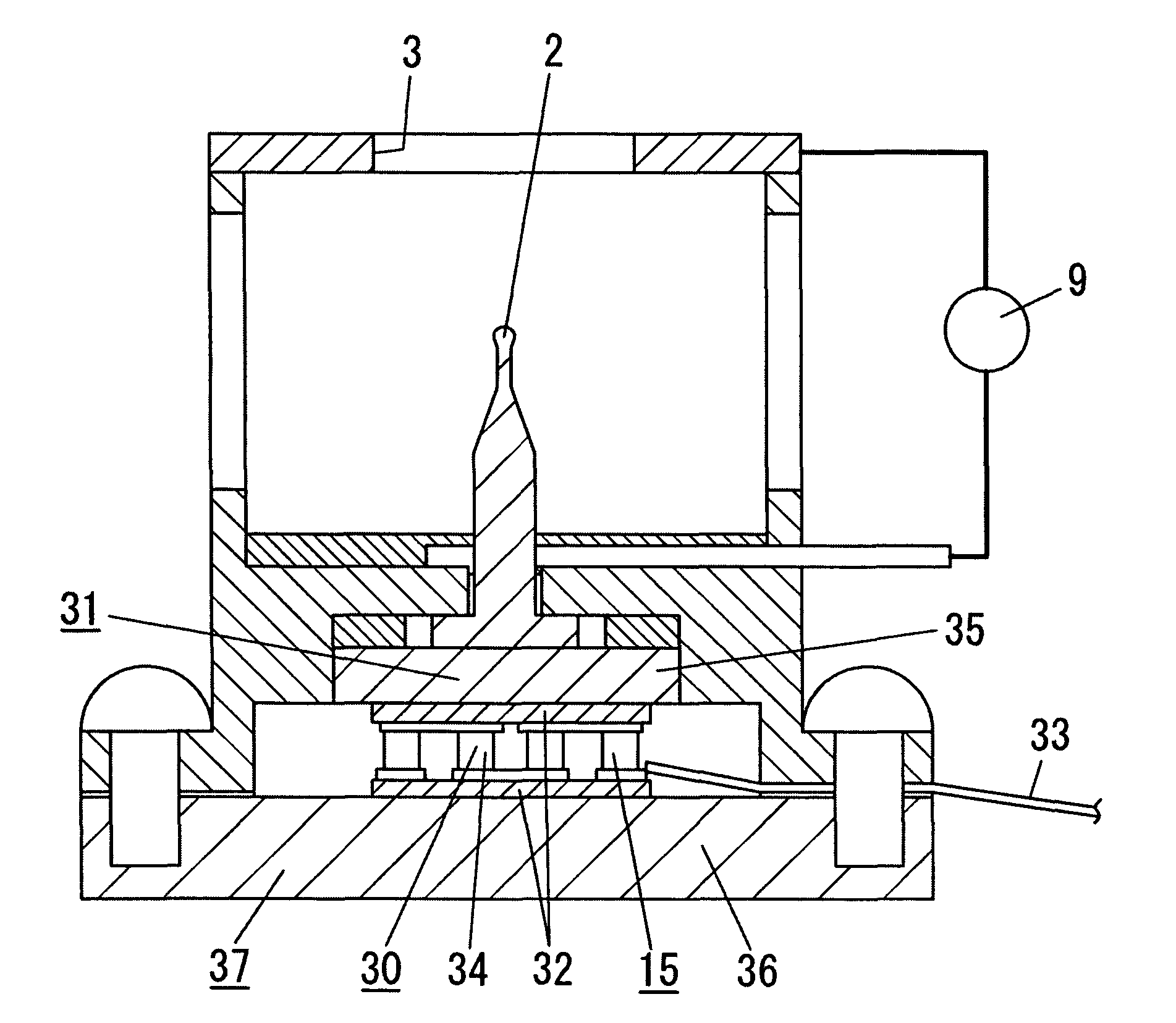
[0048]In the second embodiment illustrated in FIG. 5, the water supplier 15 has a structure where the atomizing electrode 2 is thermally connected to a cooling section 31 of a Peltier unit 30.

[0049]In the Peltier unit 30, a pair of Peltier circuit boards 32 each comprising an electrical insulation substrate made of a material having high heat conductivity, such as alumina or aluminum nitride, and a circuit formed on one surface of the electrical insulation substrate, are disposed to allow the respective circuits to be located in opposed relation to each other. A large number of n-type and p-type BiTe-based thermoelectric elements 34 disposed in an alternate arrangement are sandwiched between the Peltier circuit boards 32. Respective one ends of the adjacent thermoelectric elements 34 are electrically connected in series through a corresponding one of the opposed circuits. The Peltier unit 30 is adapted, in response to supplying a current to the thermoelectric elements 34 through a P...

third embodiment

[0055]The water supplier 15 in the third embodiment illustrated in FIG. 6 is adapted to store a liquid in a water reservoir 40 for reserving water (liquid) therein, and supply the water to a tip end of the atomizing electrode 2 by mans of a capillary phenomenon. In the embodiment, the atomizing electrode 2 is formed with a small hole or a porous portion to induce the capillary phenomenon so as to supply the water based on the capillary phenomenon. If the water reservoir 40 is located away from the atomizing electrode 2, the water may be supplied from the water reservoir 40 to the atomizing electrode 2 through a water transport member capable of inducing a capillary phenomenon.

[0056]In an operation of applying a voltage between the atomizing electrode 2 and the counter electrode 3 in such a manner as to allow a potential difference between the atomizing electrode 2 and the counter electrode 3 to be set at a given value for electrostatically atomizing water supplied onto the atomizing...


PUM


Abstract

Disclosed is an electrostatic atomizer, which comprises a high-voltage applying section adapted to apply a high voltage between an atomizing electrode and a counter electrode so as to electrostatically atomize water supplied onto the atomizing electrode, wherein the high-voltage applying section is operable to set an absolute value of a voltage to be applied to the atomizing electrode smaller than an absolute value of a voltage to be applied to the counter electrode. This allows a physical object, such as an article stored in a mist-receiving space or an inner wall of a structural member defining the mist-receiving space to become less likely to be electrostatically charged, and makes it possible to avoid causing a problem about discomfort due to discharge of static charges when a user touches the physical object.

Description

TECHNICAL FIELD[0001]The present invention relates to an electrostatic atomizer adapted to generate nanometer-size charged fine water droplets by an electrostatic atomization phenomenon and supply fine water droplets to a mist-receiving space.BACKGROUND ART[0002]There has been proposed an electrostatic atomizer comprising an atomizing electrode, a counter electrode disposed in opposed relation to the atomizing electrode, and water supplier for supplying water onto the atomizing electrode, wherein a high-voltage is applied between the atomizing electrode and the counter electrode to atomize water held on the atomizing electrode so as to generate charged fine water droplets in a nanometer size range and in a high charge state (i.e., nanometer-size electrostatically charged or ionized misty droplets), as disclosed in the following Patent Publication 1.[0003]Typically, this type of electrostatic atomizer disclosed in the Patent Publication 1 and others has been designed such that, after...

Claims


Application Information

Patent Timeline
Patent Type & Authority Patents(United States)
IPC IPC(8): B05B5/00
CPCB05B5/0533B05B5/087F25D2317/0413F25D17/042B05B5/0255B05B5/057
Inventor SUDA, HIROSHINAKADA, TAKAYUKIMACHI, MASAHARUYAMAGUCHI, TOMOHIROWADA, SUMIO
Owner PANASONIC CORP
Why Eureka
Try Eureka