Long-reach passive optical network using remote modulation of an amplification optical signal

remote modulation technology, applied in the field of optical access networks, can solve the problems of loss of optical power, limited network range, and signals being transmitted cannot be amplified to compensate such losses without incurring, and achieve the effect of reducing the operating cost of a passive optical network

Active Publication Date: 2012-08-07
FRANCE TELECOM SA
View PDF10 Cites 2 Cited by
  • Summary
  • Abstract
  • Description
  • Claims
  • Application Information

AI Technical Summary

Benefits of technology

[0023]Modulation of the second amplification optical signal by modulation means in each line termination device eliminates the active transmission means in standard line termination devices. Given the number of users that can be connected to an passive optical access network, eliminating the active transmission means in the line termination devices significantly reduces network operating costs.
[0046]Such optical components are of relatively low cost because they are in widespread use.

Problems solved by technology

This limited range is linked to the fact that in passive optical networks the optical components, for example couplers, multiplexers and optical fibers, cause signals in transit in the network to lose optical power, and the signals being transmitted cannot be amplified to compensate such losses without incurring constraints.
However, using a single optical fiber to carry the uplink and downlink optical signals introduces constraints on the power at which those optical signals are transmitted, which leads to the limited range of the network.
Those users are therefore unable to benefit from the high transmission bit rates offered by passive optical networks and thus from the services on offer that require a high bit rate connection.
However, although using passive amplification media reduces the costs of a passive optical network, passive optical access networks continue to be costly for telecommunications operators.
The terminations of such passive optical networks are equipped with numerous costly components that consume electrical power, such as lasers producing the data signals, laser diodes serving as amplification means, and active transmission means disposed in the line termination devices.
Moreover, such networks serve a large number of users, which increases the number of such components and therefore the cost of the network.

Method used


Image

  • Long-reach passive optical network using remote modulation of an amplification optical signal
  • Long-reach passive optical network using remote modulation of an amplification optical signal
  • Long-reach passive optical network using remote modulation of an amplification optical signal

Examples


first embodiment

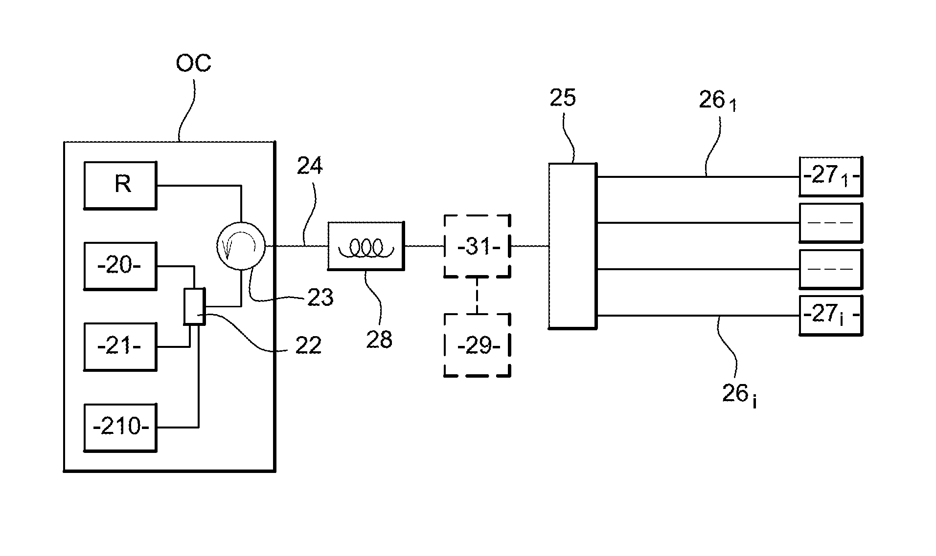
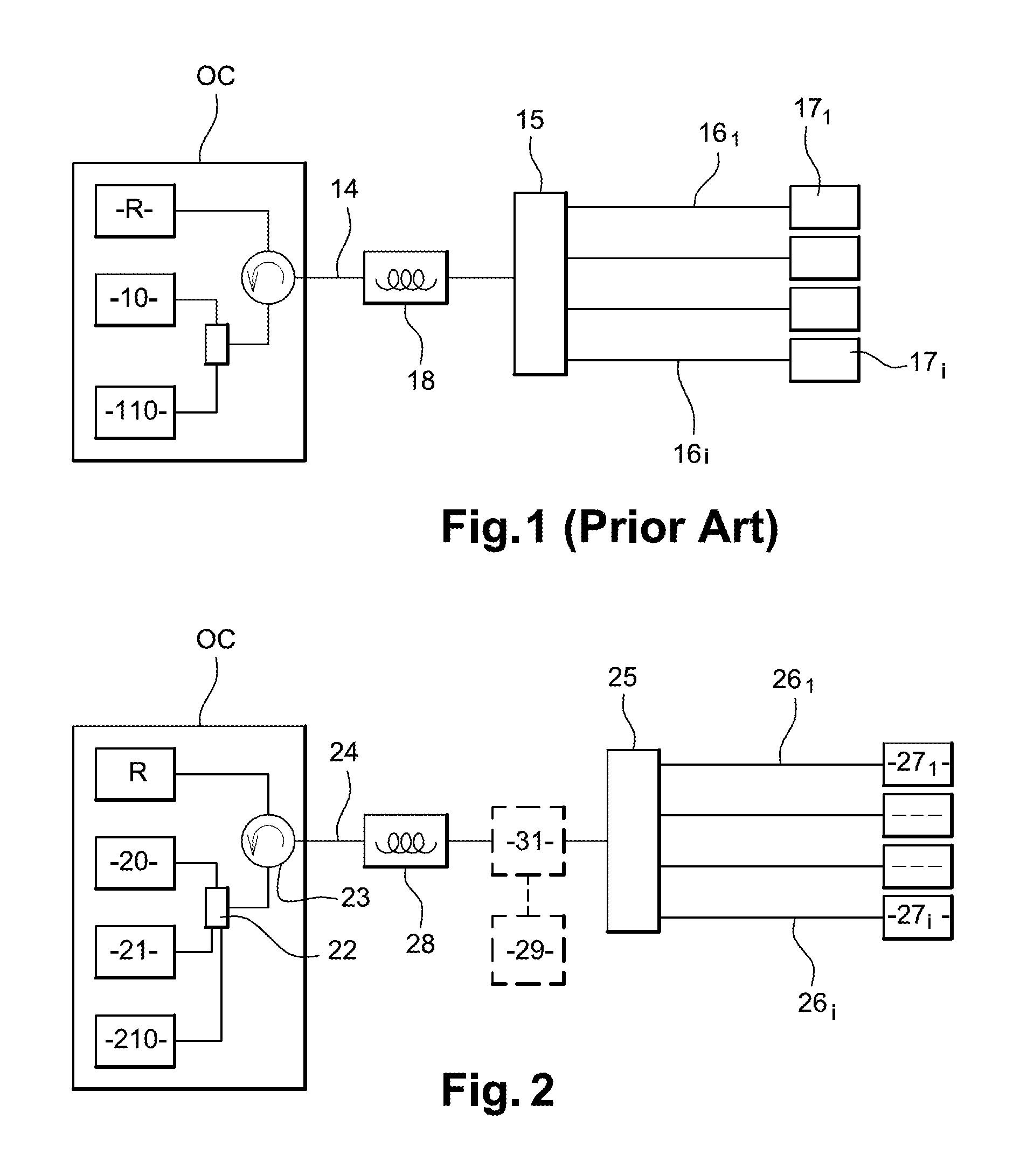
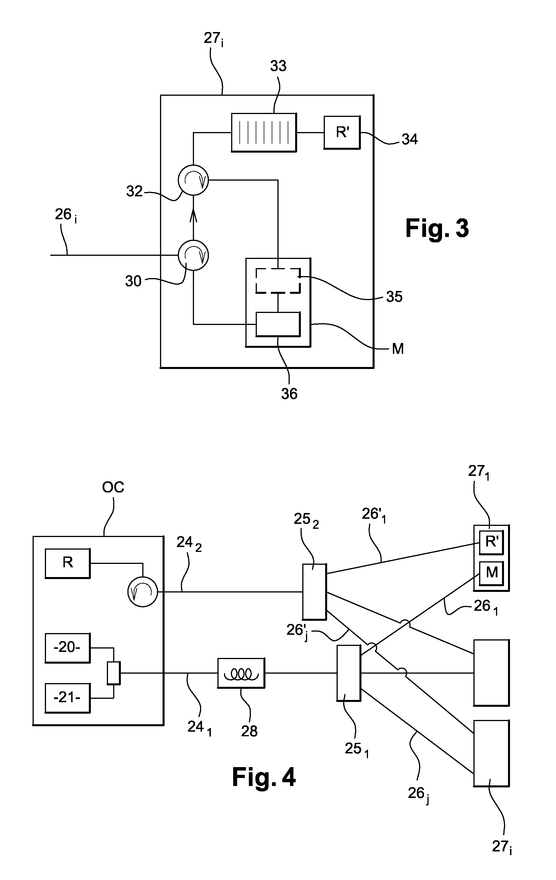
[0052]FIG. 2 represents a long-reach TDM passive optical point-to-multipoint network conforming to the invention. An optical central office OC constitutes a first end of the network. A first end of an optical fiber 24 is connected to the output of the optical central office OC. A second end of the optical fiber 24 is connected to the input of an optical coupler 25 having one input and N outputs, N representing the number of branches of the network. The optical fiber 24 is referred to as the main branch of the network. A first end of an optical fiber 26j, jε{1, 2, . . . , N}, is connected to one of the N outputs Sj of the optical coupler 25. A second end of the optical fiber 26j is connected to a line termination device 27i, iε{1, 2, . . . , N}, to which one or more users are connected. The optical fibers 261, to 26N are referred to as secondary branches of the network.

[0053]The optical central office OC includes a first laser 20 producing a first optical signal associated with a par...

second embodiment

[0068]Referring again to FIG. 2, the present invention is described. In this embodiment, the optical fiber is the only amplification medium for the data and amplification optical signals.

[0069]In this embodiment, the second amplification optical signal produced by the laser diode 210 excites the optical fiber 24 and so when the data optical signal passes through the optical fiber 24 its optical power is increased. The third amplification optical signal produced by the laser diode 21 excites the optical fiber 24 so that the optical power of the second amplification optical signal produced by the laser diode 210 is increased as it travels through the optical fiber 24.

[0070]For example, if the data optical signal is at a wavelength of 1550 nm, the second optical signal produced by the laser diode 210 must be at a wavelength of 1450 nm. To increase the optical power of the second amplification signal produced by the laser diode 210, the third amplification signal produced by the laser d...


PUM


Abstract

A passive optical network is provided, which includes an optical central office connected to a line termination device by a branch of the network including a passive amplification medium. The central office is adapted to send / receive a first data optical signal and has a first amplifier for sending a second amplification optical signal. The second signal exciting the amplification medium to amplify the optical power of an optical signal. The line termination device is adapted to receive the first optical signal, modulate the second amplification optical signal; and inject the modulated second signal into the network.

Description

CROSS-REFERENCE TO RELATED APPLICATIONS[0001]This application is a Section 371 National Stage Application of International Application No. PCT / FR2007 / 051673, filed Jul. 17, 2007 and published as WO 2008 / 009849 on Jan. 24, 2008, not in English.STATEMENT REGARDING FEDERALLY SPONSORED RESEARCH OR DEVELOPMENT[0002]None.THE NAMES OF PARTIES TO A JOINT RESEARCH AGREEMENT[0003]None.FIELD OF THE DISCLOSURE[0004]The disclosure relates to optical access networks and more particularly to access networks in the form of passive optical networks (PON).BACKGROUND OF THE DISCLOSURE[0005]Standard passive optical access networks have a range of the order of 20 kilometers (km). This limited range is linked to the fact that in passive optical networks the optical components, for example couplers, multiplexers and optical fibers, cause signals in transit in the network to lose optical power, and the signals being transmitted cannot be amplified to compensate such losses without incurring constraints. In...

Claims


Application Information

Patent Timeline
Patent Type & Authority Patents(United States)
IPC IPC(8): H04J14/00H04B10/17H04B10/2587
CPCH04B10/2587
Inventor GENAY, NAVEENAPINCEMIN, ERWANLE GUYADER, BERTRAND
Owner FRANCE TELECOM SA
Why Eureka
Try Eureka