
Centralized device virtualization layer for heterogeneous processing units

a technology of heterogeneous processing units and virtualization layers, applied in the field of device virtualization, can solve the problems of resource bottleneck, hardware device virtualization cannot be implemented in software, and hardware device virtualization cannot be implemented in hardware or software,

Active Publication Date: 2012-08-07
NVIDIA CORP
View PDF8 Cites 66 Cited by
  • Summary
  • Abstract
  • Description
  • Claims
  • Application Information

AI Technical Summary

Benefits of technology

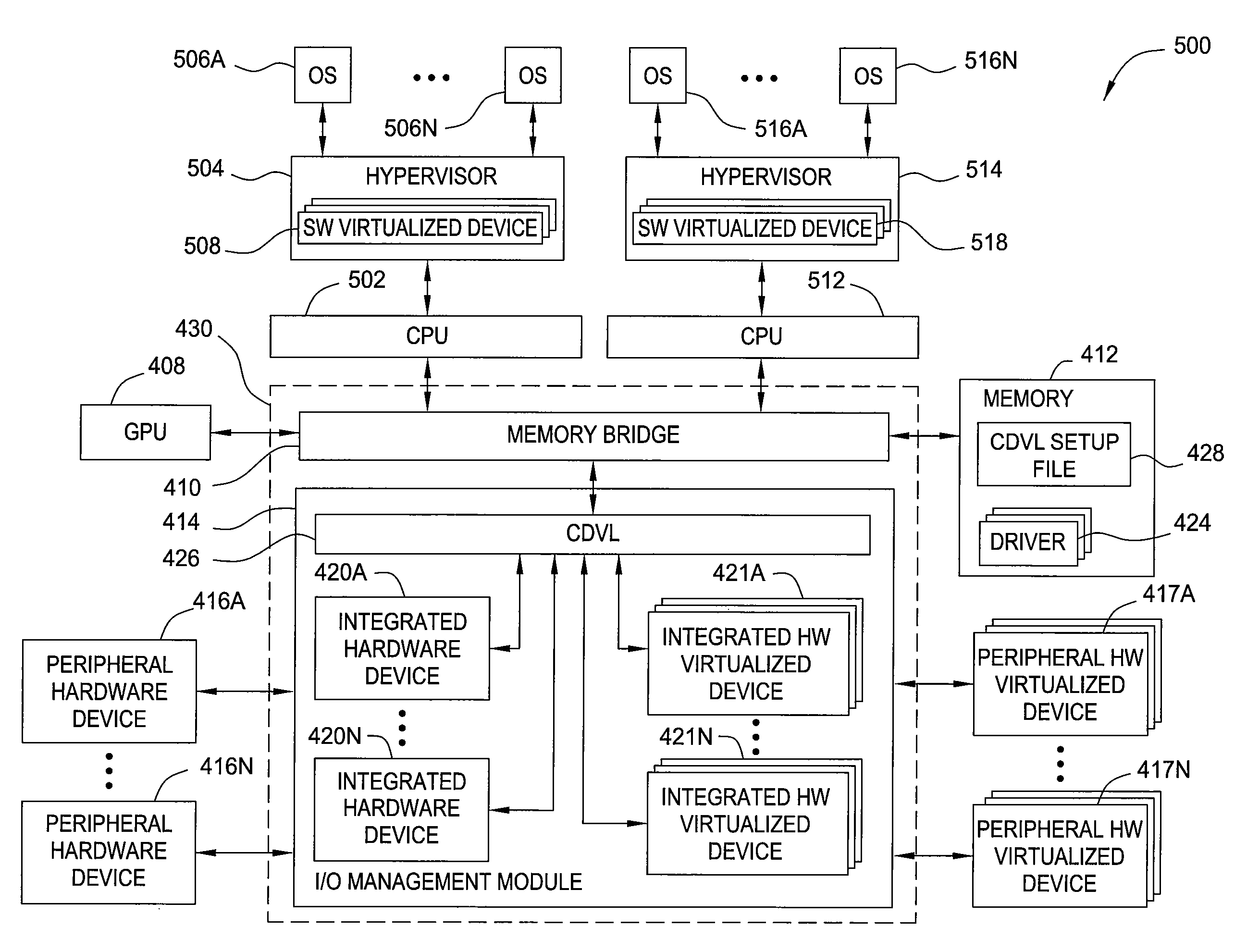
[0011]Advantageously, embodiments of the invention extend device virtualization to computing systems that include multiple CPUs. The CDVL allows OSs executing on each CPU to access a common pool of enumerated devices that are coupled to the computing system. The CDVL may be used in conjunction with SW virtualization and HW virtualization to provide dedicated virtualization support to an OS that requires such support.

Problems solved by technology

However, more diverse processor topologies that include multiple CPUs executing multiple OSs are less amenable to SW virtualization and / or HW virtualization.
Some hardware devices cannot be virtualized in hardware or in software, thus, the computer system includes only one resource for that hardware device that cannot be shared by two CPUs.
Implementing SW virtualization in a multi-CPU computer system is also problematic because bottlenecks can be created when an OS wants to access a SW virtualized hardware device that is being underutilized.
A resource bottleneck is created because resources of the hardware device are still available, but the OS cannot utilize these resources because they have been allocated to other guest physical resources.
Implementing HW virtualization in a multi-CPU computer system is also problematic because a virtualized device would need to be created for each OS running on each CPU.

Method used


Image

  • Centralized device virtualization layer for heterogeneous processing units
  • Centralized device virtualization layer for heterogeneous processing units
  • Centralized device virtualization layer for heterogeneous processing units

Examples


Embodiment Construction

[0021]In the following description, numerous specific details are set forth to provide a more thorough understanding of the invention. However, it will be apparent to one of skill in the art that the invention may be practiced without one or more of these specific details. In other instances, well-known features have not been described in order to avoid obscuring the invention.

System Overview

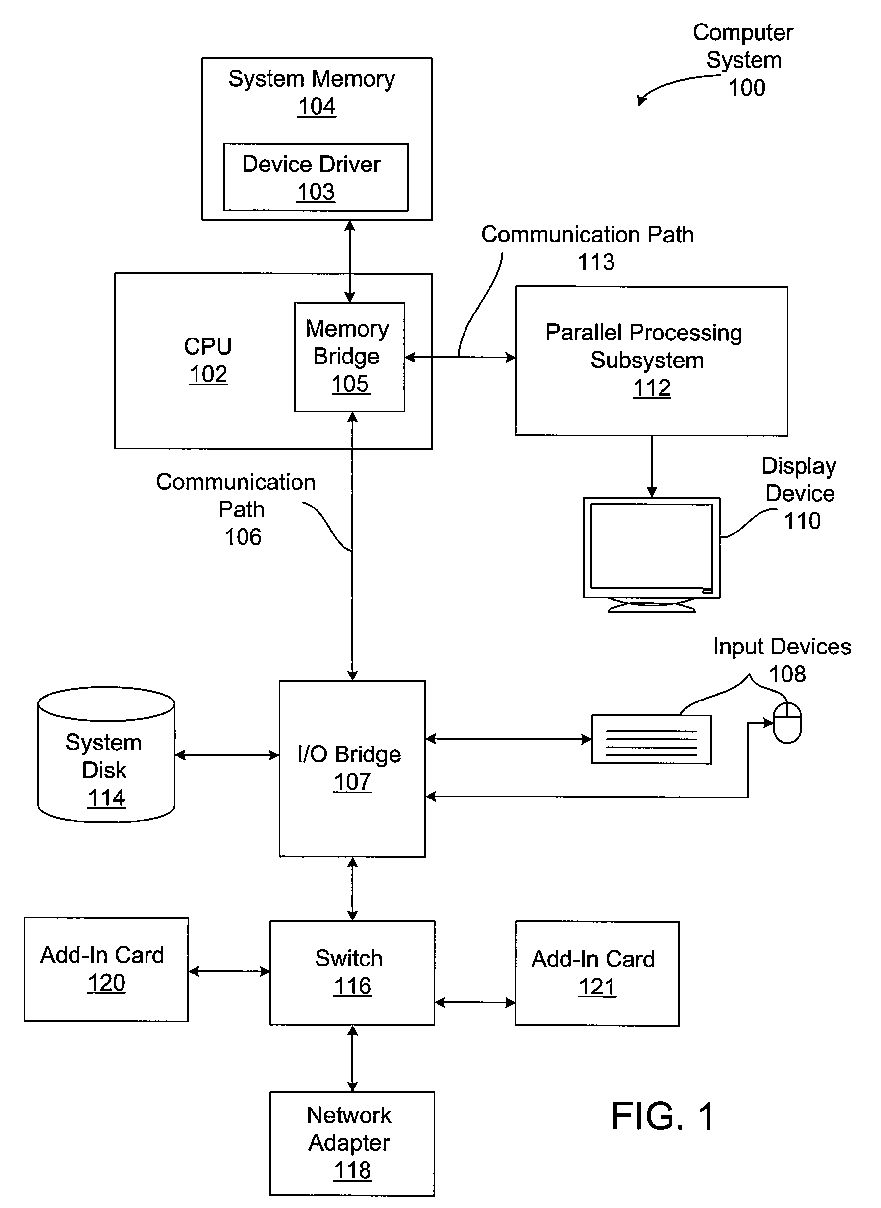
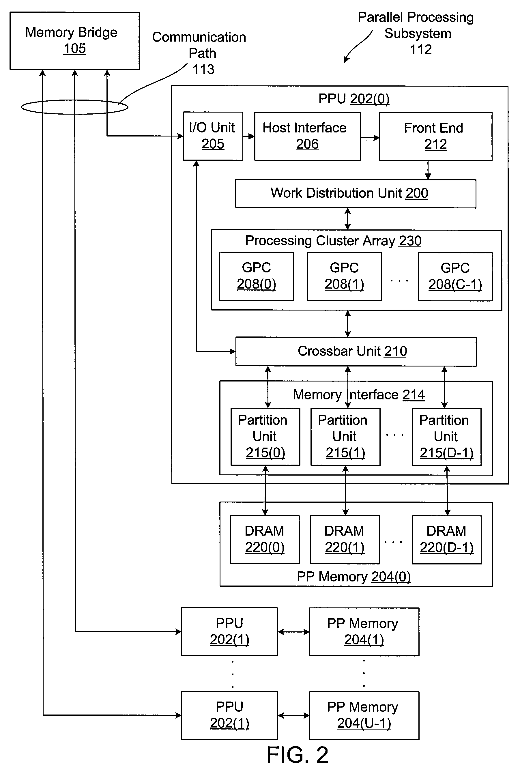
[0022]FIG. 1 is a block diagram illustrating a computer system 100 configured to implement one or more aspects of the invention. Computer system 100 includes a central processing unit (CPU) 102 and a system memory 104 communicating via a bus path through a memory bridge 105. Memory bridge 105 may be integrated into CPU 102 as shown in FIG. 1. Alternatively, memory bridge 105, may be a conventional device, e.g., a Northbridge chip, that is connected via a bus to CPU 102. Memory bridge 105 is connected via communication path 106 (e.g., a HyperTransport link) to an I / O (input / output) bridge 107. I / ...


PUM


Abstract

A method for providing an operating system access to devices, including enumerating hardware devices and virtualized devices, where resources associated with a first hardware device are divided into guest physical resources creating a software virtualized device, and multiple instances of resources associated with a second hardware device are advertised thereby creating a hardware virtualized device. First and second permission lists are generated that specify which operating systems are permitted to access the software virtualized device and the hardware virtualized device, respectively. First and second sets of virtual address maps are generated, where each set maps an address space associated with either the software virtualized device or the hardware virtualized device into an address space associated with each operating system included in the corresponding permission list. The method further includes arbitrating access requests from each of the plurality of operating systems based on the permission lists and the virtual address maps.

Description

BACKGROUND OF THE INVENTION[0001]1. Field of the Invention[0002]The present invention relates generally to the field of device virtualization and, more specifically, to a centralized device virtualization layer for heterogeneous processing units.[0003]2. Description of the Related Art[0004]In a conventional computer system, a central processing unit (CPU) is capable of executing multiple operating systems (OSs). A software program known as a “hypervisor” is often used to coordinate the operations of the different OSs. The hypervisor manages input / output (I / O) access operations (accesses) transmitted from each OS to various hardware devices included in the computer system. These hardware devices may include memory modules, computer monitors, hard disk drives, and CD-ROM drives, among others. The hypervisor allows each of the OSs to access the hardware devices using a technique known as “device virtualization,” which may be used to create virtual instances of a hardware device. A hard...

Claims


Application Information

Patent Timeline
Patent Type & Authority Patents(United States)
IPC IPC(8): G06F12/00G06F13/00G06F12/14
CPCG06F9/45537G06F9/06G06F9/28G06F9/50
Inventor SIMERAL, BRAD W.COX, MICHAEL BRIAN
Owner NVIDIA CORP
Learn More