
Detahcable hand rail for a recreational vehicle

a technology for recreational vehicles and handrails, which is applied in the direction of scaffold accessories, vehicular safety arrangments, building scaffolds, etc., can solve the problems of lack of suitable stability for users, difficulty in providing handrails, and difficulty in accessing elderly, disabled, etc., and achieves convenient installation, removal, storage

Inactive Publication Date: 2012-08-14
RAWLS JAMES L
View PDF13 Cites 6 Cited by
  • Summary
  • Abstract
  • Description
  • Claims
  • Application Information

AI Technical Summary

Benefits of technology

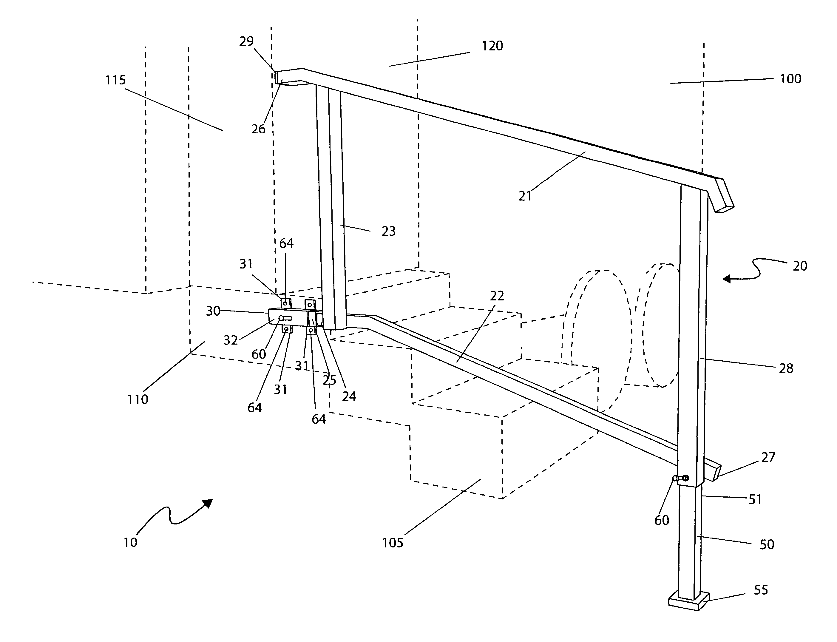
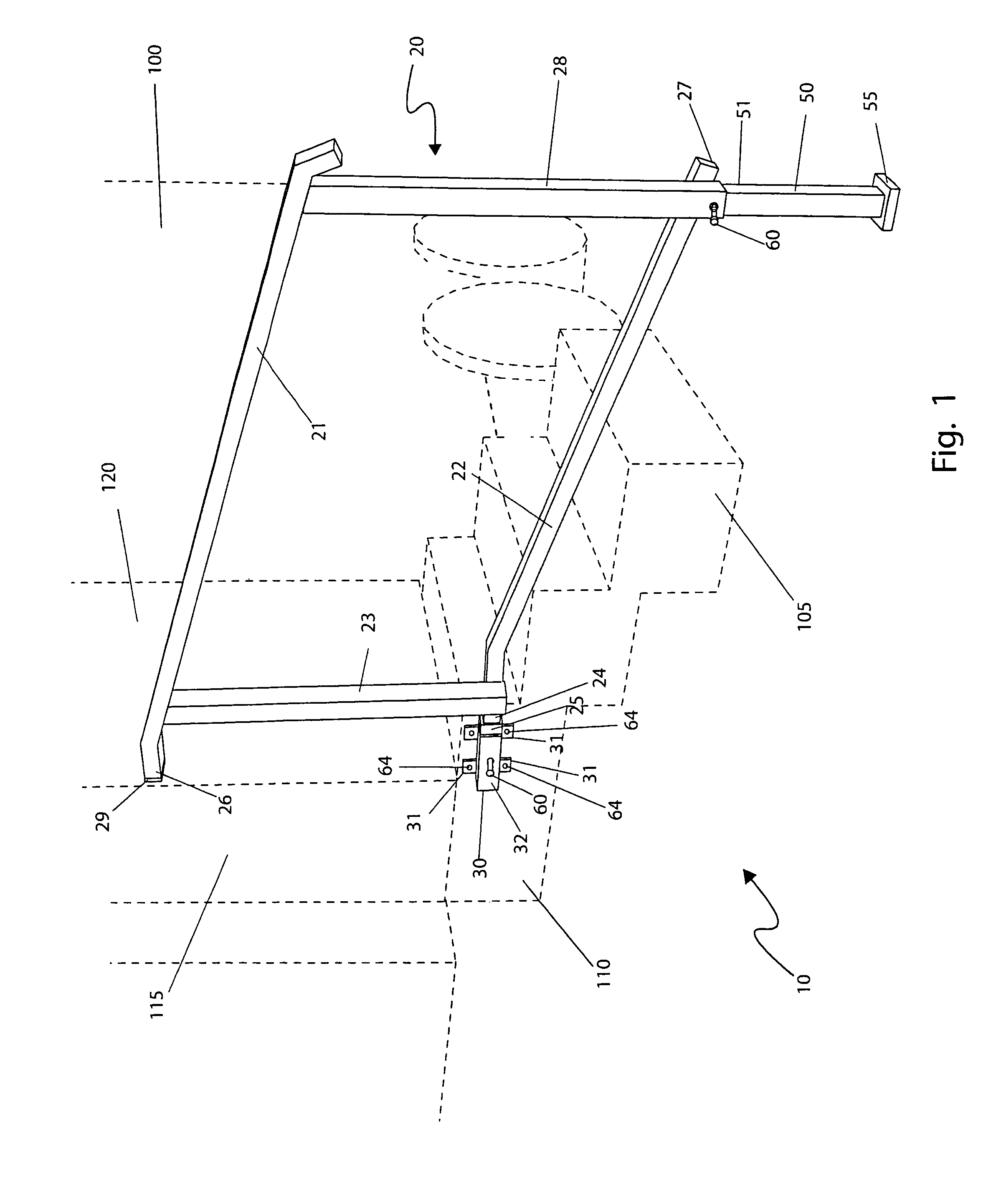
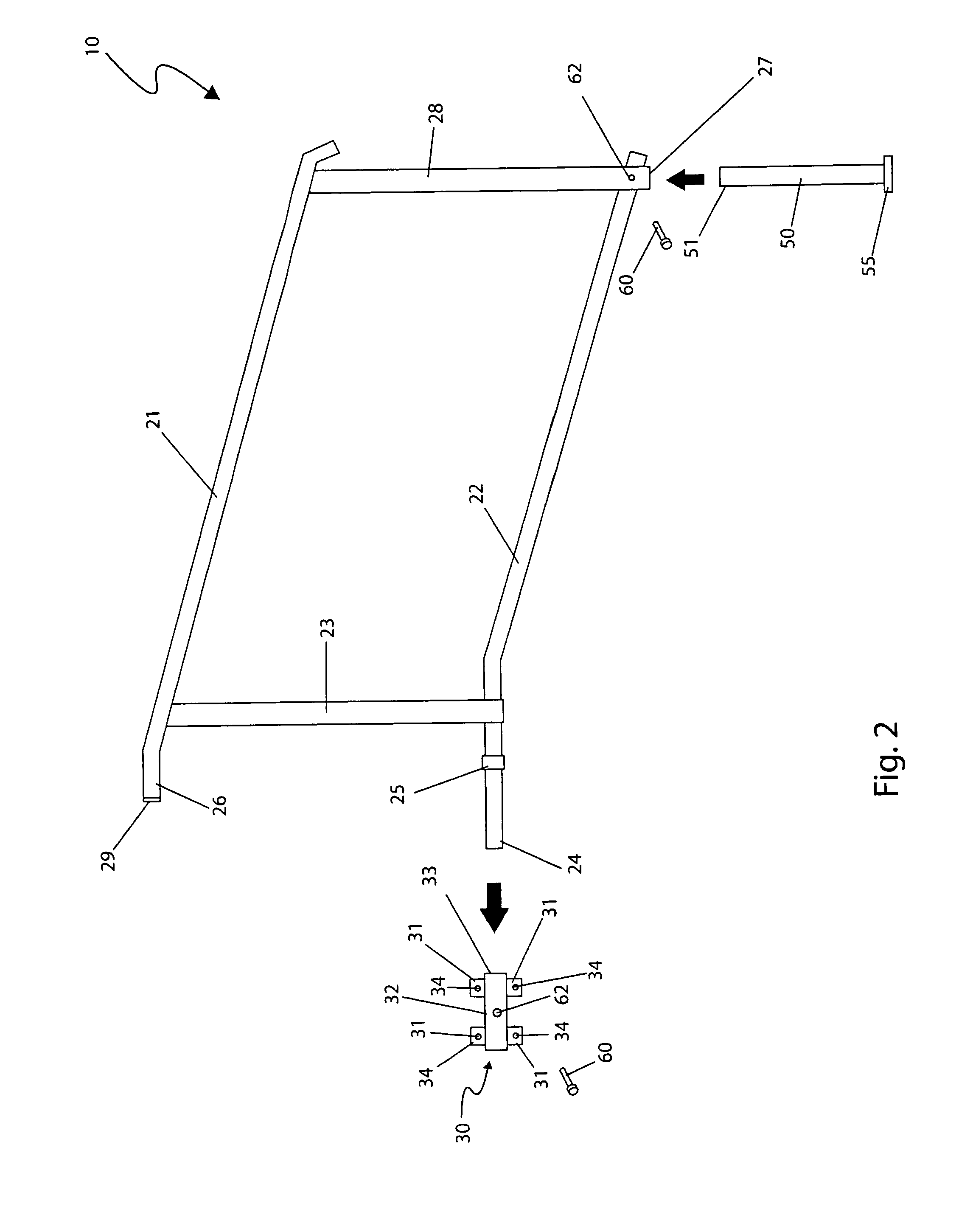
[0012]To achieve the above objectives, it is an object of the present invention to provide a detachable hand rail for a recreational vehicle that provides a means for easily attaching and detaching a rail assembly along a set of access steps that is intended to be used with motor homes, fifth wheels, travel trailers, campers, and any similar vehicle which have one (1) or more access steps.
[0021]Yet still another object of the detachable hand rail for a recreational vehicle is to provide a method of utilizing the device that provides access to recreational vehicle interiors in a manner which is not only quick, easy and effective, but safe as well.

Problems solved by technology

However, hand rails are typically not provided.
Typically these attachable hand rails also swing out when in use and fold away when not in use and are ordinarily unstable and come no where near the bottom of the steps, at grade level, where a conventional permanent stairway hand rail would be located.
Thus, access for the elderly, disabled, and the like is extremely difficult and often times hazardous.
While these devices fulfill their respective, particular objectives, each of these references suffers from the one (1) or more of the common disadvantages of most attachable hand rails, which includes complex mechanical mounting assemblies, a lack of suitable stability to a user, and a deficiency in size to provide support to and from ground level.

Method used


Image

  • Detahcable hand rail for a recreational vehicle
  • Detahcable hand rail for a recreational vehicle
  • Detahcable hand rail for a recreational vehicle

Examples


Embodiment Construction

[0031]The best mode for carrying out the invention is presented in terms of its preferred embodiment, herein depicted FIGS. 1 through 6. However, the invention is not limited to the described embodiment, and a person skilled in the art will appreciate that many other embodiments of the invention are possible without deviating from the basic concept of the invention and that any such work around will also fall under scope of this invention. It is envisioned that other styles and configurations of the present invention can be easily incorporated into the teachings of the present invention, and only one particular configuration shall be shown and described for purposes of clarity and disclosure and not by way of limitation of scope.

[0032]The terms “a” and “an” herein do not denote a limitation of quantity, but rather denote the presence of at least one of the referenced items.

[0033]The present invention describes a detachable hand rail for a recreational vehicle (herein described as th...


PUM


Abstract

A removable handrail system for recreational vehicles and similar vehicles is herein disclosed, located and installed along side steps of said vehicles and used to access the door or other similar location. It is intended for use on motor homes, fifth wheels, travel trailers, truck campers and virtually any vehicle which utilizes one (1) or more steps for access and comprises a hitch-like receiver assembly that mounts on the side of the step assembly directly underneath the door or upper platform. The handrail slides into the receiver and is secured via a locking bolt. The handrail is adjustable to compensate for varying grades. When fully installed, the device is supported at two (2) points and forms a very stable handrail for entering and exiting the vehicle. It is quickly installed and removed with a minimum of tools and can be stored in a narrow storage compartment when not in use.

Description

RELATED APPLICATIONS[0001]The present invention was first described in a notarized Official Record of Invention filed on Mar. 24, 2008 at the offices of Montgomery Patent and Design in Washington, Pa. There are no previously filed, nor currently any co-pending applications, anywhere in the world.FIELD OF THE INVENTION[0002]The present invention relates generally to handrail assemblies for stairs and steps and, more particularly, to an attachable hand rail and bracket assembly for use with vehicle entryway steps.BACKGROUND OF THE INVENTION[0003]Millions of Americans enjoy camping and traveling as their preferred leisure time activity. A great number of these people choose to do so in recreational vehicles (RV's) that range in size from small pop-up campers that are designed to be towed behind a car or truck to large motorized RV's with integral engines. Most of these vehicles have a floor system that is several feet about ground level. As such, they must be accessed with a step syste...

Claims


Application Information

Patent Timeline
Patent Type & Authority Patents(United States)
IPC IPC(8): B60R99/00
CPCB60R3/005
Inventor RAWLS, JAMES L.
Owner RAWLS JAMES L
Learn More