Device for controlling hydraulic braking of a trailer hitched to a tractor

Inactive Publication Date: 2012-08-14
POCLAIN HYDRAULICS IND
View PDF9 Cites 13 Cited by
  • Summary
  • Abstract
  • Description
  • Claims
  • Application Information

AI Technical Summary

Problems solved by technology

Braking control devices of this type are subjected to contradictory requirements.
Such adaptation op

Method used


Image

  • Device for controlling hydraulic braking of a trailer hitched to a tractor
  • Device for controlling hydraulic braking of a trailer hitched to a tractor
  • Device for controlling hydraulic braking of a trailer hitched to a tractor

Examples


Embodiment Construction

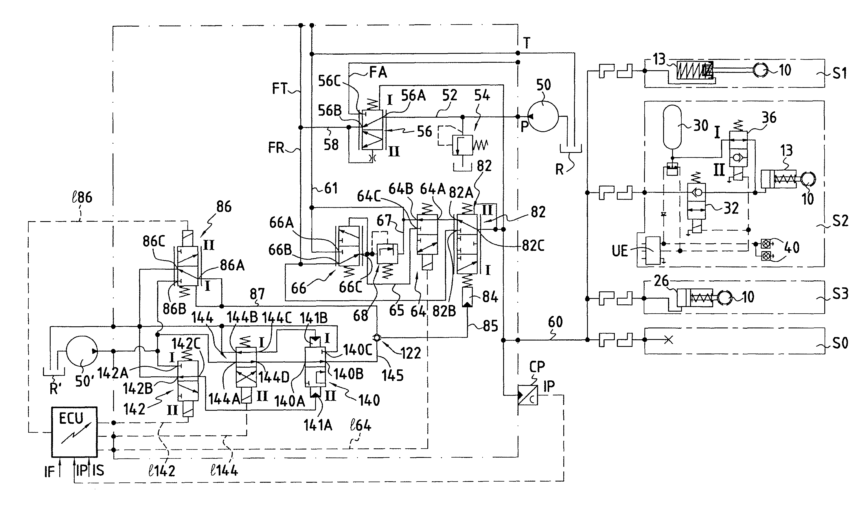
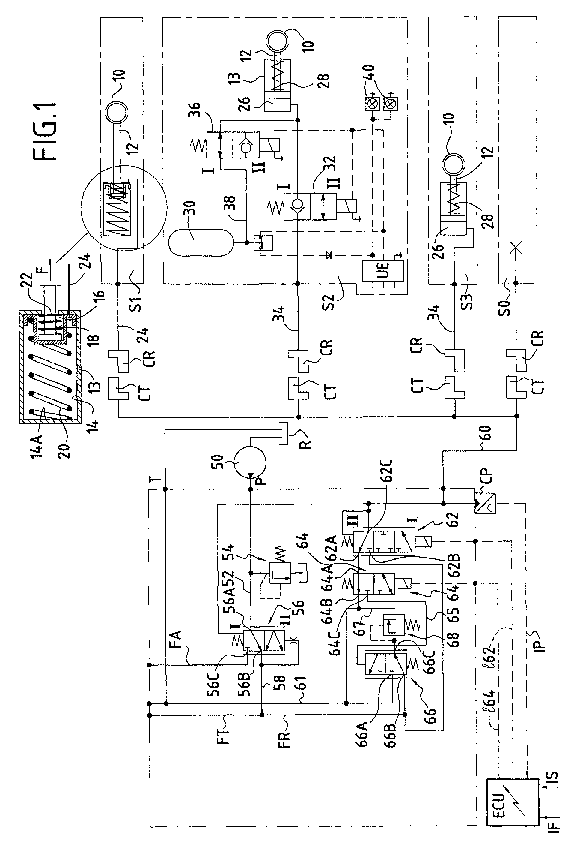
[0026]Firstly, the right portion of FIG. 1 is described. That portion shows the possible examples of trailer braking systems S1, S2, S3 and shows a situation S0 in which no trailer is hitched to the tractor.

[0027]System S1 is of the Italian type. It comprises mechanical brake members, e.g. brake linings 10 that must be moved apart against the inside periphery of a hub in order to perform braking. They are controlled by a hydraulic actuator system comprising a piston 12 mounted to move in a cylinder 13, and hydraulic control means which, as can be seen more clearly in the enlargement, comprise a main enclosure 14 and a secondary enclosure 16. The secondary enclosure 16 is defined, inside the main enclosure, by a moving cup 18 that is urged continuously in the braking direction by a main return spring 20. The rod of the piston 12 is urged continuously towards the end wall of the cup by a secondary spring 22. A hydraulic pipe 24 is connected to the main enclosure 14. It can be understa...


PUM


Abstract

A hydraulic circuit having a brake pipe suitable for being connected to a pressurized fluid source or to a pressure-free reservoir, i.e. to a reservoir without excess pressure, via a proportional pressure reducer controlled by an electronic control unit (ECU). The circuit includes link solenoid-valve means suitable for connecting the proportional pressure reducer to the reservoir or, via a calibrated pressure reducer, to the pressurized fluid source.

Description

BACKGROUND OF THE INVENTION[0001]The present invention relates to a device for controlling hydraulic braking of a trailer hitched to a tractor, which device comprises a hydraulic circuit having a brake pipe suitable for being connected to a pressurized fluid source or to a pressure-free reservoir, i.e. a reservoir without excess pressure, via a proportional pressure reducer controlled by control means comprising an electronic control unit.[0002]Such a device can serve for braking trailers of various types, in particular farm trailers. Trailers of the “Italian” type exist in which the brake can be activated in a parking situation (i.e. in a rest situation) through lack of pressure in a hydraulic control chamber, whereas it is deactivated in order to enable the trailer to move when a medium pressure (e.g. in the range 8 bars to 15 bars) is maintained in that chamber, and it is reactivated for service braking (i.e. braking while the trailer is moving) when the pressure reaches a much h...

Claims


Application Information

Patent Timeline
IPC IPC(8): B60T13/14
CPCB60T13/686
Inventor HEREN, JEANPRIGENT, ANDRERAISIN, JEAN-PHILIPPE
Owner POCLAIN HYDRAULICS IND
Why Eureka
Try Eureka