Check patentability & draft patents in minutes with Patsnap Eureka AI!

Patch panel assembly and patching module thereof

a technology for patching modules and patch panels, applied in the direction of coupling device connections, coupling device details, contact members penetrating/cutting insulation/cable strands, etc., to achieve the effect of convenient assembly, convenient manufacturing, and convenient assembly

Inactive Publication Date: 2012-08-14
SURTEC INDS
View PDF5 Cites 8 Cited by
  • Summary
  • Abstract
  • Description
  • Claims
  • Application Information

AI Technical Summary

Benefits of technology

This design simplifies production, enhances assembly efficiency, allows for flexible expansion or reduction of connection ports, and enables cost-effective maintenance by allowing replacement of individual modules rather than the entire panel, while providing improved tool compatibility and reduced production complexity.

Problems solved by technology

When a patching module fails or is damaged, the user can perform replacement or maintenance only after taking out the failed or damaged patching module.

Method used


Image

  • Patch panel assembly and patching module thereof
  • Patch panel assembly and patching module thereof
  • Patch panel assembly and patching module thereof

Examples


Embodiment Construction

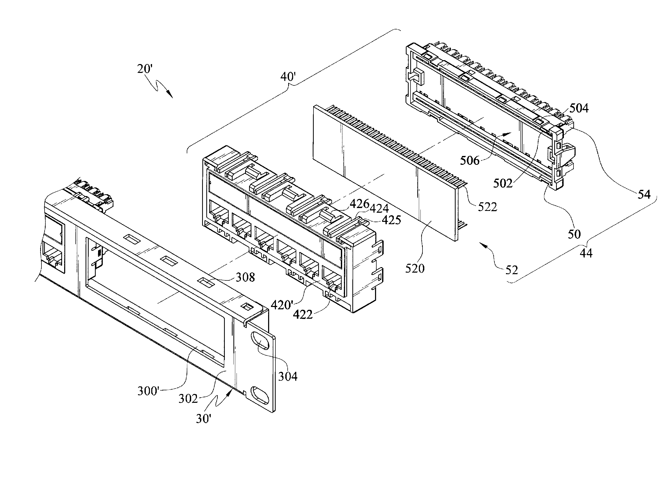
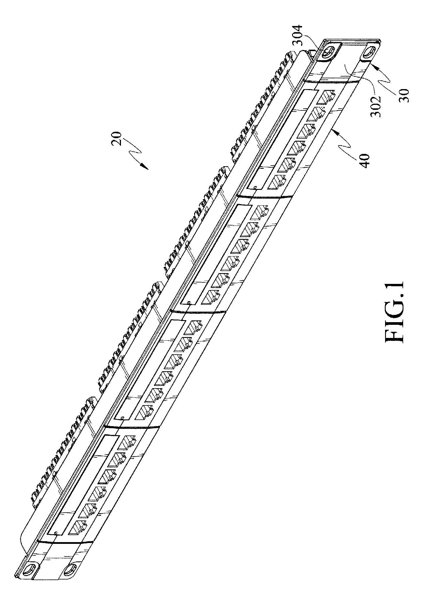
[0026]Referring to FIG. 1, a patch panel assembly 20 according to an embodiment of the present invention is shown. The patch panel assembly 20 comprises an outer frame 30 and multiple patching modules 40. The outer frame 30 has a setting port 300, and the more than one patching module 40 is disposed in the setting port 300. The outer frame 30 comprises at least one front wing panel 302. The front wing panel 302, extending from a lateral margin of the outer frame 30 by a predetermined width, can have at least one fixing hole 304, and fix the patch panel assembly 20 by the fixing hole 304.

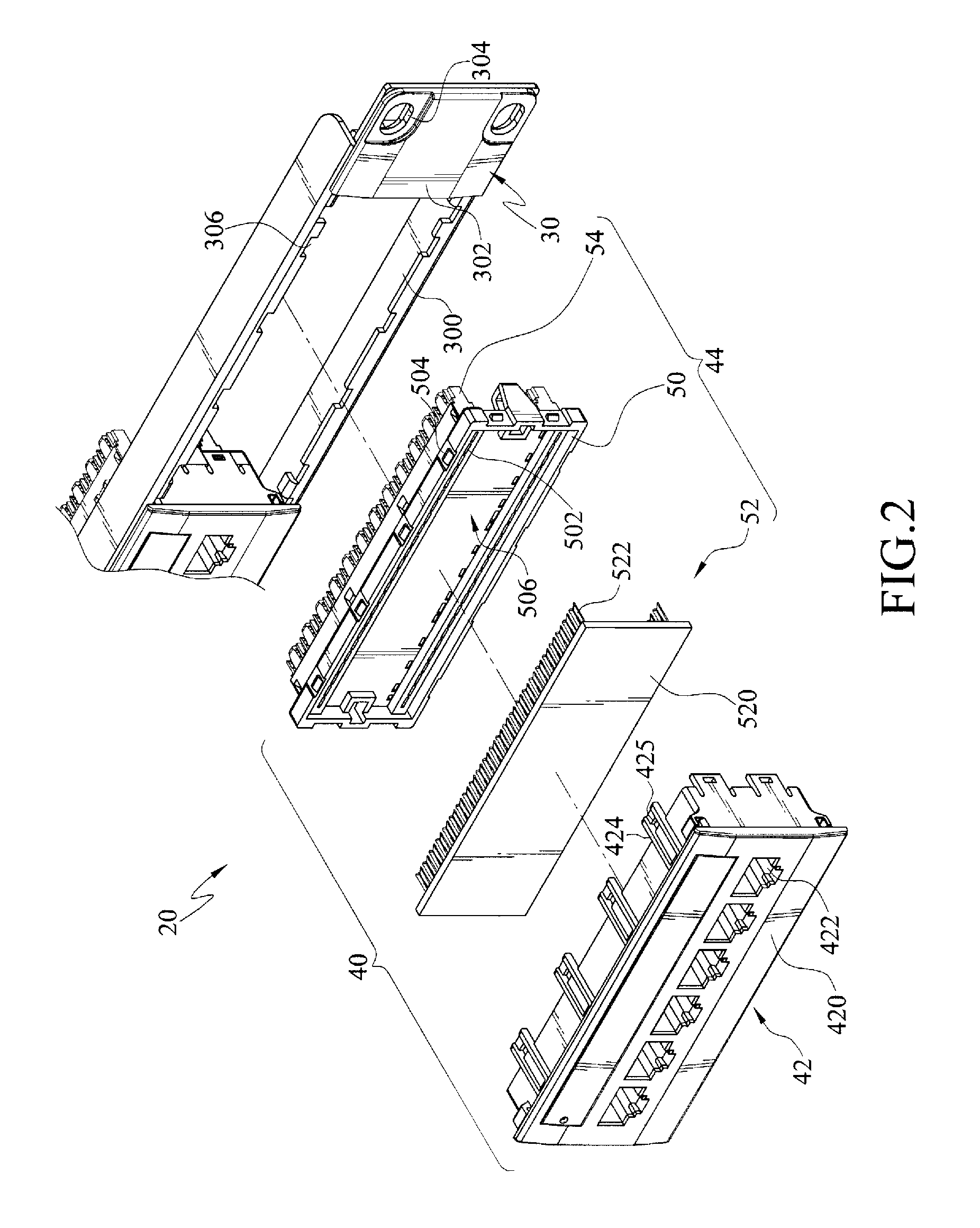
[0027]Referring to FIG. 2, a patching module 40 according to an embodiment of the present invention is shown, which comprises an RJ component 42 and an IDC component 44. The RJ component 42 comprises a front base 420 and a plurality of RJ jacks 422 disposed on the front base 420. The area of the front side of the front base 420 is larger than the area of the setting port 300 of the outer frame 30, so...


PUM


Abstract

A patch panel assembly and a patching module thereof are described. The patch panel assembly includes an outer frame and more than one patching module disposed on the outer frame. The patching module includes a registered jack (RJ) component and an insulation displacement contact (IDC) component which can be combined correspondingly, so that a plurality of RJ jacks and a plurality of IDC pins are electrically connected and assembled on the outer frame. The IDC component can further match two specifications of punch down tools to perform compression and wire bonding.

Description

BACKGROUND OF THE INVENTION[0001]1. Field of Invention[0002]The present invention relates to a patch panel for communication, and more particularly to a patch panel assembly having an outer frame and more than one patching module, and a patching module thereof.[0003]2. Related Art[0004]A patch panel for communication is always used for connecting multiple transmission lines. Multiple registered jacks (RJ jacks) are usually disposed in the front of the patch panel, for the transmission lines with RJ pins to plug. Multiple insulation displacement contact (IDC) holders are disposed at the rear side of the patch panel for connecting and fixing the transmission lines. A user can adjust the connection relationship of the transmission lines connected in the front of and at the rear side of the patch panel quickly by replacing the transmission lines connected in the front of the patch panel, so as to change the communication and transmission path.[0005]A known patch panel for communication ...

Claims


Application Information

Patent Timeline
Patent Type & Authority Patents(United States)
IPC IPC(8): H01R4/24
CPCH01R4/245H01R13/518H01R13/6658H01R13/743H01R24/64H04Q1/09H04Q1/13H01R12/515
Inventor CHEN, CHOU-HSING
Owner SURTEC INDS
Features
  • R&D
  • Intellectual Property
  • Life Sciences
  • Materials
  • Tech Scout
  • Unparalleled Data Quality
  • Higher Quality Content
  • 60% Fewer Hallucinations
Learn More