Manual device for massaging appendage muscles

a manual device and appendage technology, applied in the field of massage devices, can solve the problems of inconvenient portability, cumbersome devices, and inability to truly massaging, and achieve the effect of convenient portability and small siz

Active Publication Date: 2012-08-14
LITTON KEVIN SCOTT +1
View PDF7 Cites 10 Cited by
  • Summary
  • Abstract
  • Description
  • Claims
  • Application Information

AI Technical Summary

Benefits of technology

[0012]It is an object of the invention to provide a portable, manual, non-electric device for massaging appendage muscles. Accordingly, the present device is made from lightweight materials, is small in size and easy to carry, and requires no electrical inputs.
[0014]It is an object of the invention to provide a massaging device which is easy to use. Accordingly, the present device requires the user to simply encircle the desired body part with the wrap and apply compressions to the actuator to relieve muscle tension in the body part.
[0015]It is an object of the invention to provide a low cost massaging device in manufacturing and a low-cost end product. Accordingly, the present device is manufactured using simple materials and parts which are readily available.
[0017]It is an object of the invention to provide a massaging device for contracting and expanding around a body part. Accordingly, the present device allows the user to compress and decompress the actuator which retracts and releases, respectively, the tension-transfer member and thereby contracts and expands the wrap around the body part to relieve muscle tension.
[0020]It is an object of the invention to provide a massaging device which is comfortable while in use. Accordingly, in the present device a protective flap is positioned under the tension-transfer members and springs so as to avoid abrasion between the springs and operators skin.

Problems solved by technology

This, again, is not a true massaging device.
It also requires electricity, in the form of a battery, which can be inconvenient for many people, and the device may cost more than someone other than those already afflicted with deep vein thrombosis or at a high risk for this condition may be willing to spend.
However, most are cumbersome devices which are not portable and are cost prohibitive except for use in clinical environments.
These are also medical devices, rather expensive, and are primarily for those people already with deep vein thrombosis or those with a high risk of this condition.

Method used


Image

  • Manual device for massaging appendage muscles
  • Manual device for massaging appendage muscles
  • Manual device for massaging appendage muscles

Examples


Embodiment Construction

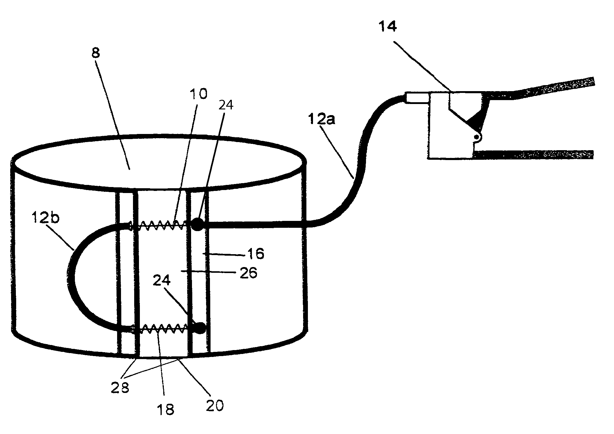
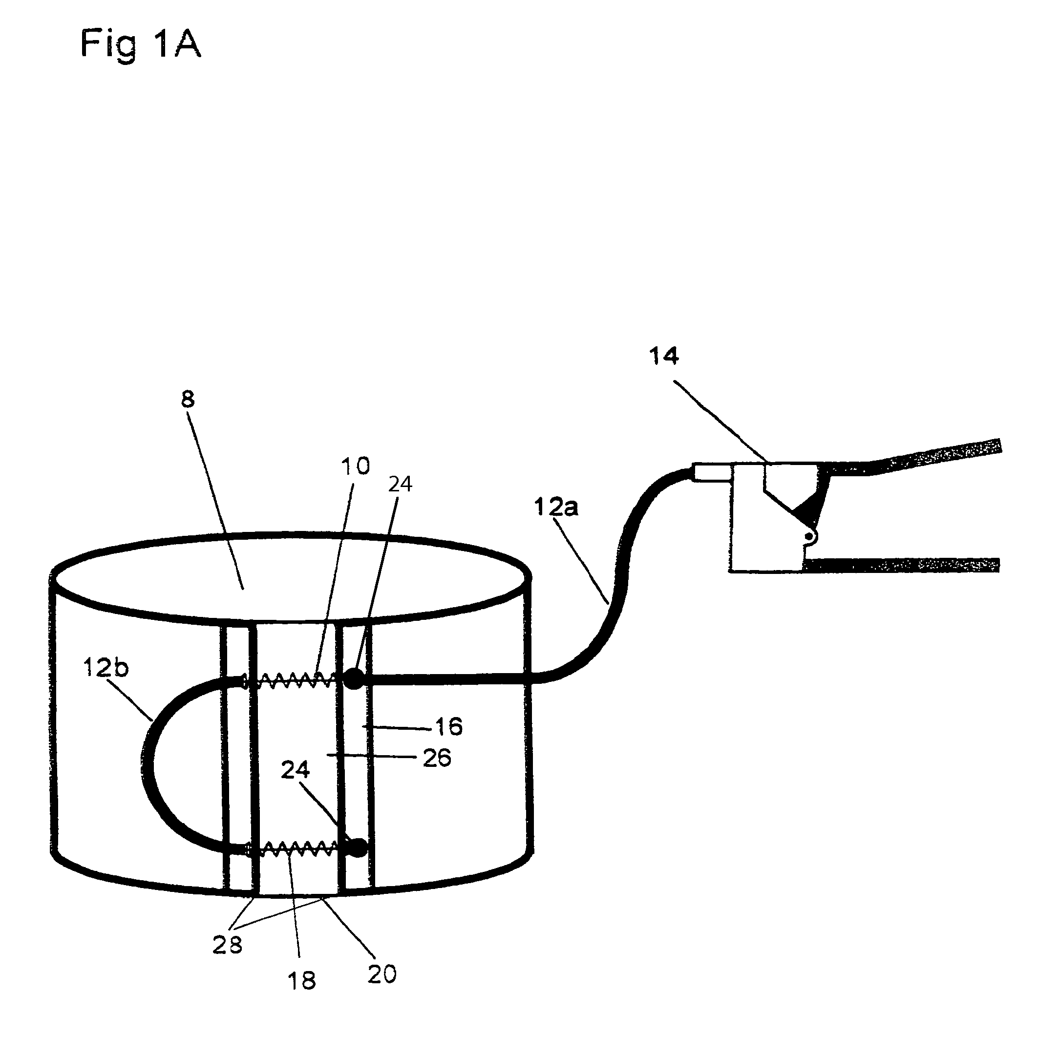
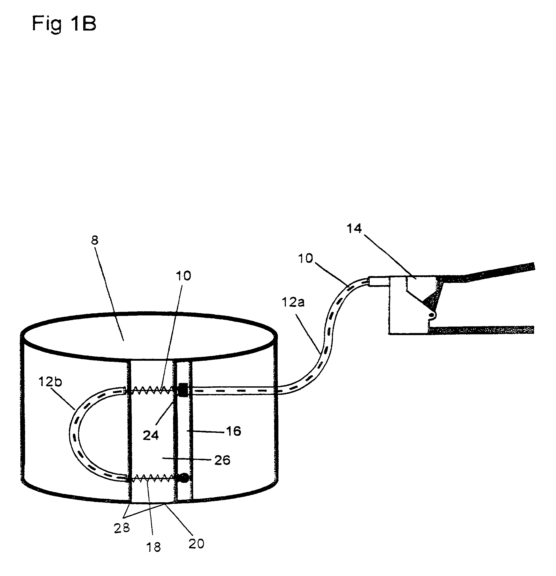
[0044]FIG. 1 illustrates the massaging device in the preferred embodiment. The massaging device has a wrap 8 made of a soft, flexible material, preferably nylon. It is possible for the wrap 8 to be made of a variety of materials, such as, canvas, polyester, or the like. The wrap 8 can also be made of semi-soft material, such as rubber or leather, or a hard material, such as metal or plastic. For wraps 8 made of soft or semi-soft materials, one or more straight or curved wrap supporters 16 can be attached to the vertical edges 28 of the wrap 8 along the vertical axis to allow for even compression and to prevent the wrap 8 to “pucker” along the vertical edges 28.

[0045]The wrap 8 has vertical edges 28 and a gap 26 defined by the vertical edges 28 which allows the wrap 8 to be constricted. The size of the gap 26 is preferably two to three centimeters, but can be varied. The vertical edges 28 of the wrap 8 are bound by a tension-transfer member 10. Preferably, the tension-transfer member...


PUM


Abstract

A portable, manual massage device for massaging appendage muscles, having a wrap with vertical edges and a gap defined between the vertical edges. The vertical edges have at least one anchor and are bound by at least one tension transfer member located between the vertical edges. The tension transfer members are encircled with springs between the vertical edges and enclosed by an external tension-transfer guide and an internal tension-transfer guide. The external tension-transfer guide integrally couples between an actuator and the wrap and the internal tension-transfer guide integrally couples between the anchors.

Description

CROSS-REFERENCE TO RELATED APPLICATION[0001]This application claims the benefit of provisional patent application Ser. No. U.S. 61 / 000,196 filed Oct. 25, 2007 by the present inventors, which is incorporated by reference.BACKGROUND OF THE INVENTION[0002]The invention relates to a massaging device, and more particularly, to a personal, manual massaging device for appendage muscles comprised of a wrap, wherein the wrap having vertical edges separated by a gap is bound by at least one tension transfer member enclosed by internal and external tension-transfer guides, the tension transfer member is encircled with springs between the vertical edges, and the external tension-transfer guide is connected to an actuator, and a method of massaging appendage muscles using the manual device.[0003]Muscle tension is caused from a variety of sources, such as, extreme or fast bodily movement, strain on muscle use, stress, injury or trauma to the body, etc. Muscle tension can also be caused by interna...

Claims


Application Information

Patent Timeline
Patent Type & Authority Patents(United States)
IPC IPC(8): A61H23/00
CPCA61H11/00A61H2011/005
Inventor LITTON, KEVIN SCOTTWALSH, JONATHAN SCOTT
Owner LITTON KEVIN SCOTT
Why Eureka
Try Eureka