

Noncollimated 3D radioactive source localization technique
- Summary
- Abstract
- Description
- Claims
- Application Information
AI Technical Summary
Benefits of technology
Problems solved by technology
Method used
Image

Examples
Embodiment Construction
[0002]1. Field of the Invention
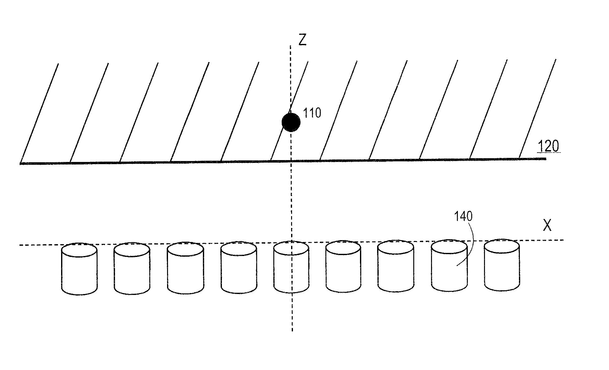
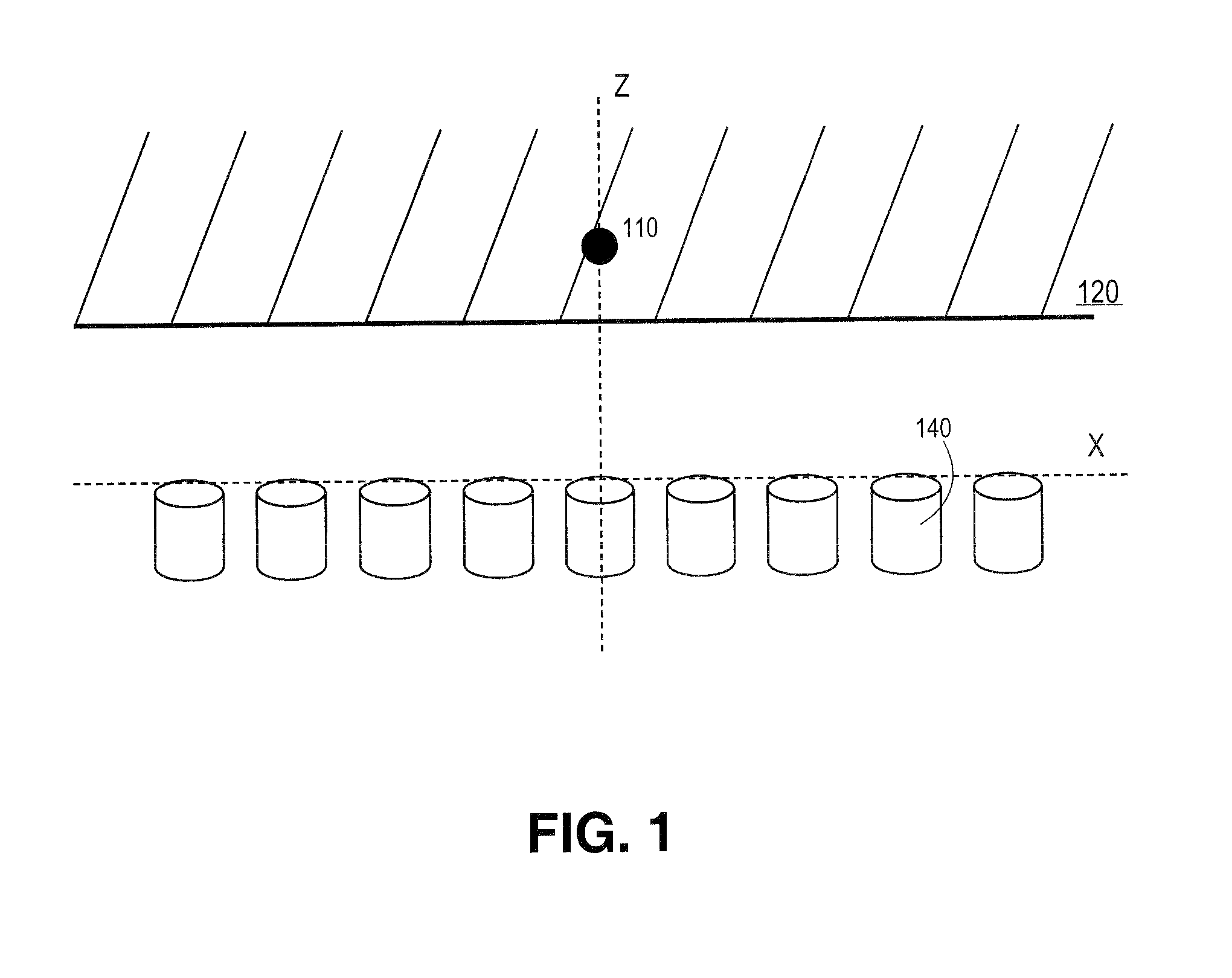
[0003]This invention relates generally to detection of a radioactive source and, more particularly, to use of a non-collimated localization technique for determining position and strength information of an unknown radioactive source.
[0004]2. Background of the Invention
[0005]Conventional techniques for localizing a radioactive source include positron emission tomography (PET) and computed temomgraphy (CT). For example, with PET medical imaging, back-to-back x-rays are emitted from a source within the body which is surrounded by detectors. For CT imaging, the x-rays are emitted from a known position outside the body and fired through the body towards the detectors. In a single photon emission CT imaging (SPECT), photons may be emitted from within the body and the detector is collimated to only allow photons from the same angle to be detected.
[0006]In all these conventional techniques, the angle of photons hitting the detector must be known or set either ...
PUM
 Abstract
Description
Claims
Application Information