Earth fill retaining wall system and method

Active Publication Date: 2012-08-21
HALL H CARL +1
View PDF5 Cites 16 Cited by
  • Summary
  • Abstract
  • Description
  • Claims
  • Application Information

AI Technical Summary

Benefits of technology

[0011]It is further object of the invention to provide a system and method of constructing a retainer wall th

Problems solved by technology

The tools, forms and construction methods used to construct these retai

Method used


Image

  • Earth fill retaining wall system and method
  • Earth fill retaining wall system and method
  • Earth fill retaining wall system and method

Examples


Example

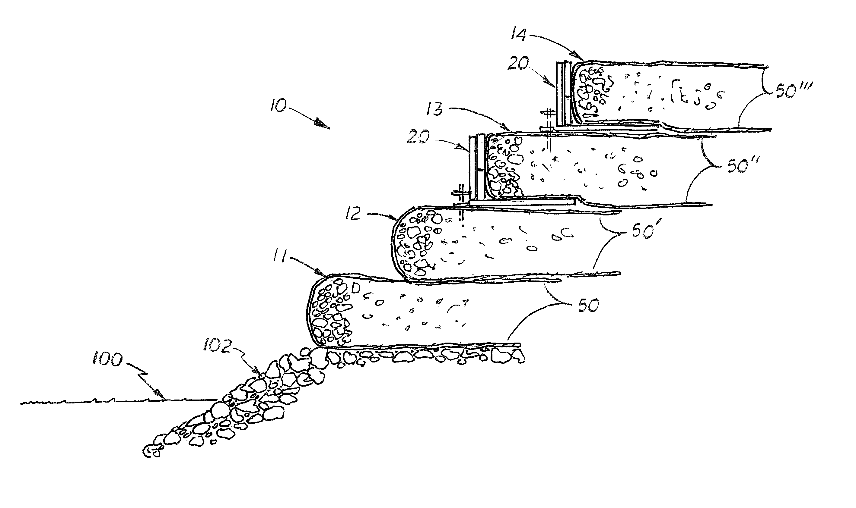
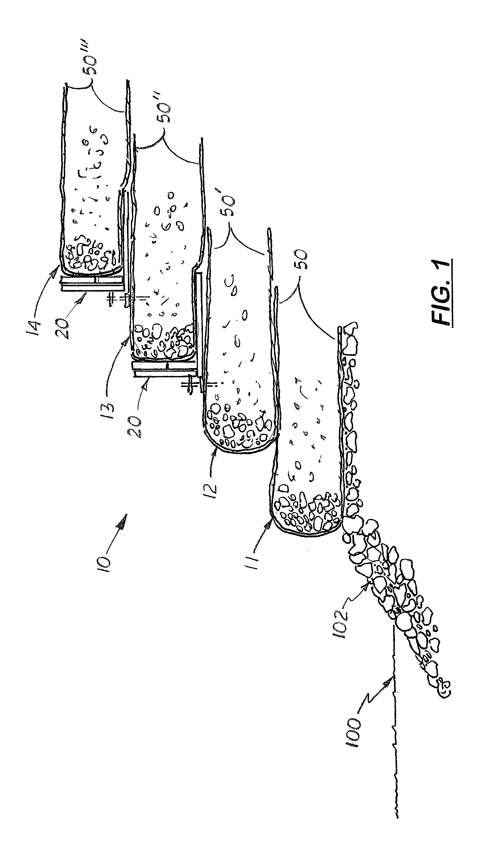
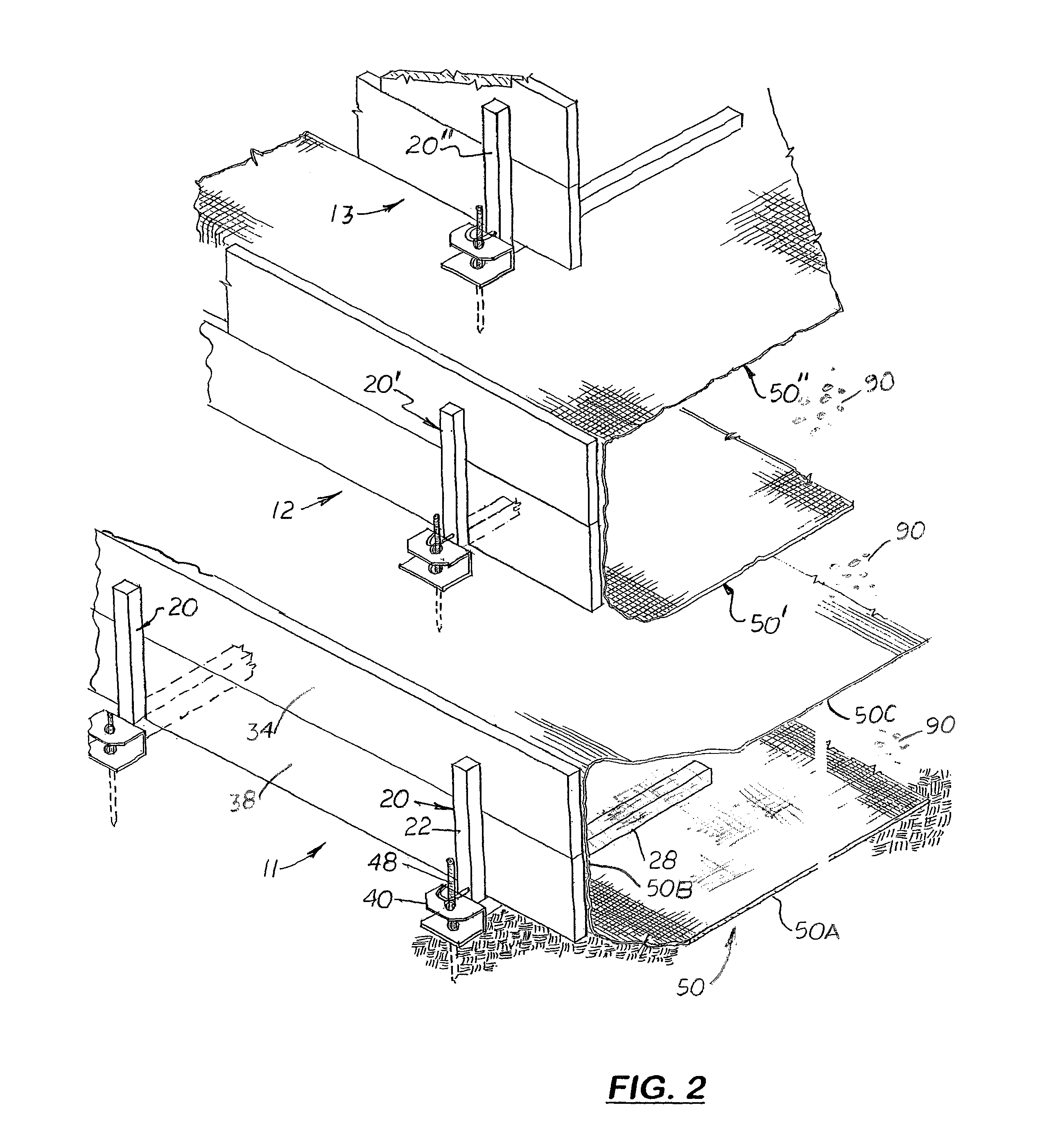
[0027]Referring to the accompanying Figs., there is shown an earth fill retaining wall system, generally indicated by the reference number 10, made up of a plurality of stepped and stacked retaining wall tiers 11, 12, 13, and 14 (see FIG. 1). Each retaining wall tier 11, 12, 13, and 14 are constructed using a plurality of removable brackets 20 that supports horizontally aligned support boards 34, 38 against the exposed middle section of a mesh cover panel 50 used to hold earth fill material 90. As shown more clearly in FIGS. 2-4, in the first embodiment, the bracket 20 is an L-shaped structure that includes a vertical post 22 and a perpendicularly aligned base 28 attached to its lower end. During assembly, the vertical post 22 is placed over the outside surface of two horizontally aligned form support boards 34, 38, stacked on edge over the inside corner of the base 28. Each bracket 20 is arranged on the ground so that the post 22 extends upward and the base 28 extends rearward into...


PUM


Abstract

An earth fill retaining wall system that uses a removable L-shaped bracket and one or more support boards that temporarily holds the front surface of a mesh cover panel vertical aligned while backfilled with fill material. The brackets hold the mesh cover panel until tiers are stacked above. The weight of the stack tiers are used to hold the mesh cover panel on each lower tier in place. Once the above stacked tiers are formed, the brackets can be removed and reused. Attached to the lower end of the post and extending in the opposite direction of the base is an optional support shoe. A hole is formed in the shoe that receives a vertical stake or pin driven into the ground to temporarily hold the bracket in place. Attached to the post is a loop that attaches to a chain or cable used to pull the bracket forward.

Description

COPYRIGHT NOTICE[0001]Notice is hereby given that the following patent document contains original material which is subject to copyright protection. The copyright owner has no objection to the facsimile or digital download reproduction of all or part of the patent document, but otherwise reserves all copyrights whatsoever.[0002]This utility patent application is based on and claims the filing date of the provisional patent application (Ser. No. 61 / 190,841) filed on Sep. 2, 2008.BACKGROUND OF THE INVENTION[0003]1. Field of the Invention[0004]This invention pertains to the field of earth filled retaining walls systems and methods, and more particularly to retaining wall systems and methods designed to be constructed in environmentally sensitive areas.[0005]2. Description of the Related Art[0006]Roadways and trails are commonly constructed over or adjacent to rivers and streams. State and federal environmental laws and regulations control how the retaining walls will be constructed and...

Claims


Application Information

Patent Timeline
IPC IPC(8): E02D29/02
CPCE02D17/20
Inventor HALL, H. CARLHALL, HOWARD CARL
Owner HALL H CARL
Why Eureka
Try Eureka