Method and apparatus for frit sealing with a variable laser beam

a variable laser beam and frit technology, applied in the manufacture of electrode systems, cold cathode manufacturing, electric discharge tubes/lamps, etc., can solve the problems of reducing the useful life of oleds, oleds are susceptible to damage, and the conventional oled manufacturing is very expensive, so as to improve the utilization of frit width and strength, the effect of uniform temperature distribution

a variable laser beam and frit technology, applied in the manufacture of electrode systems, cold cathode manufacturing, electric discharge tubes/lamps, etc., can solve the problems of reducing the useful life of oleds, oleds are susceptible to damage, and the conventional oled manufacturing is very expensive, so as to improve the utilization of frit width and strength, the effect of uniform temperature distribution

US8247730B2Inactive Publication Date: 2012-08-21CORNING INC

Image

  • Method and apparatus for frit sealing with a variable laser beam
  • Method and apparatus for frit sealing with a variable laser beam
  • Method and apparatus for frit sealing with a variable laser beam

Examples


Embodiment Construction

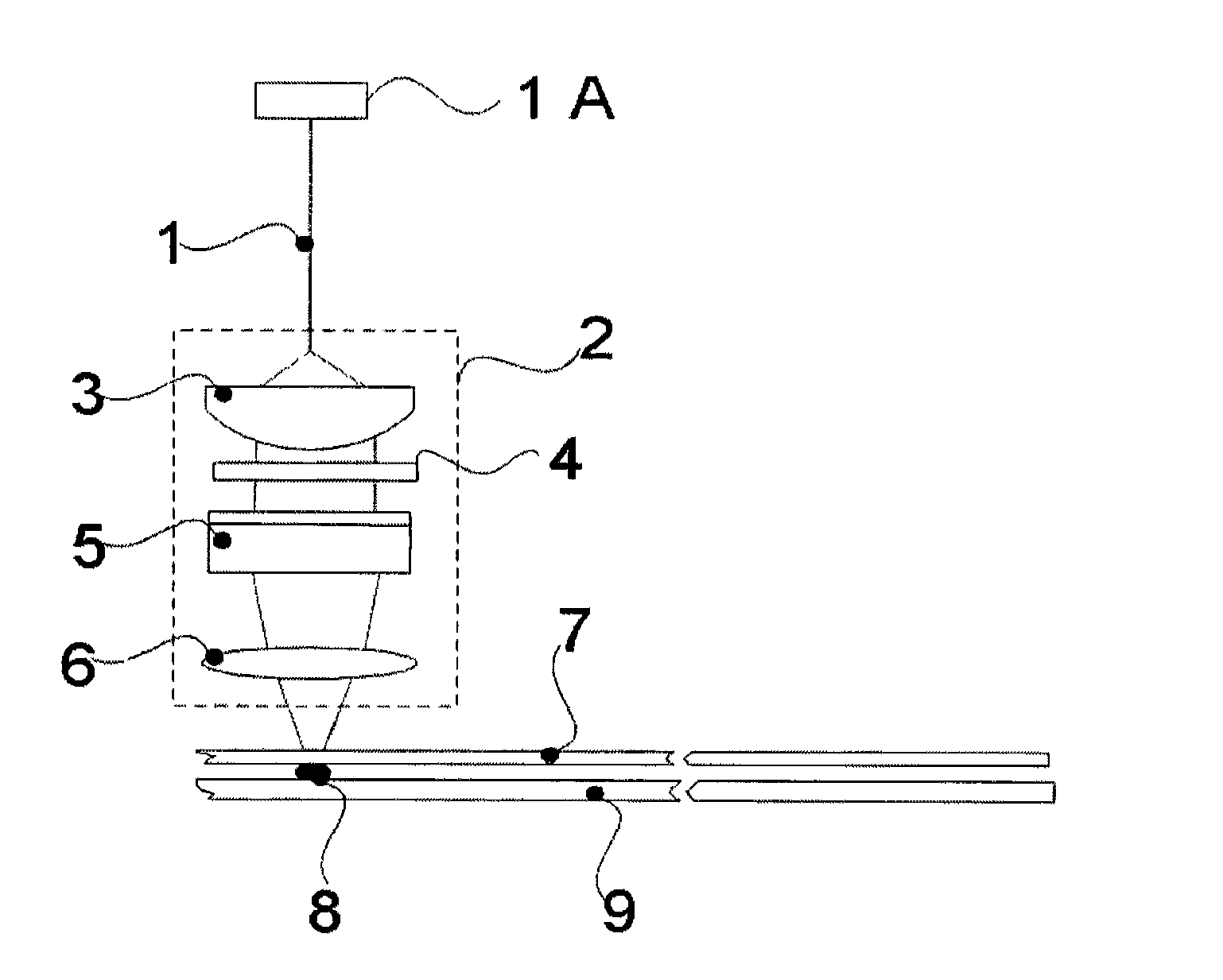
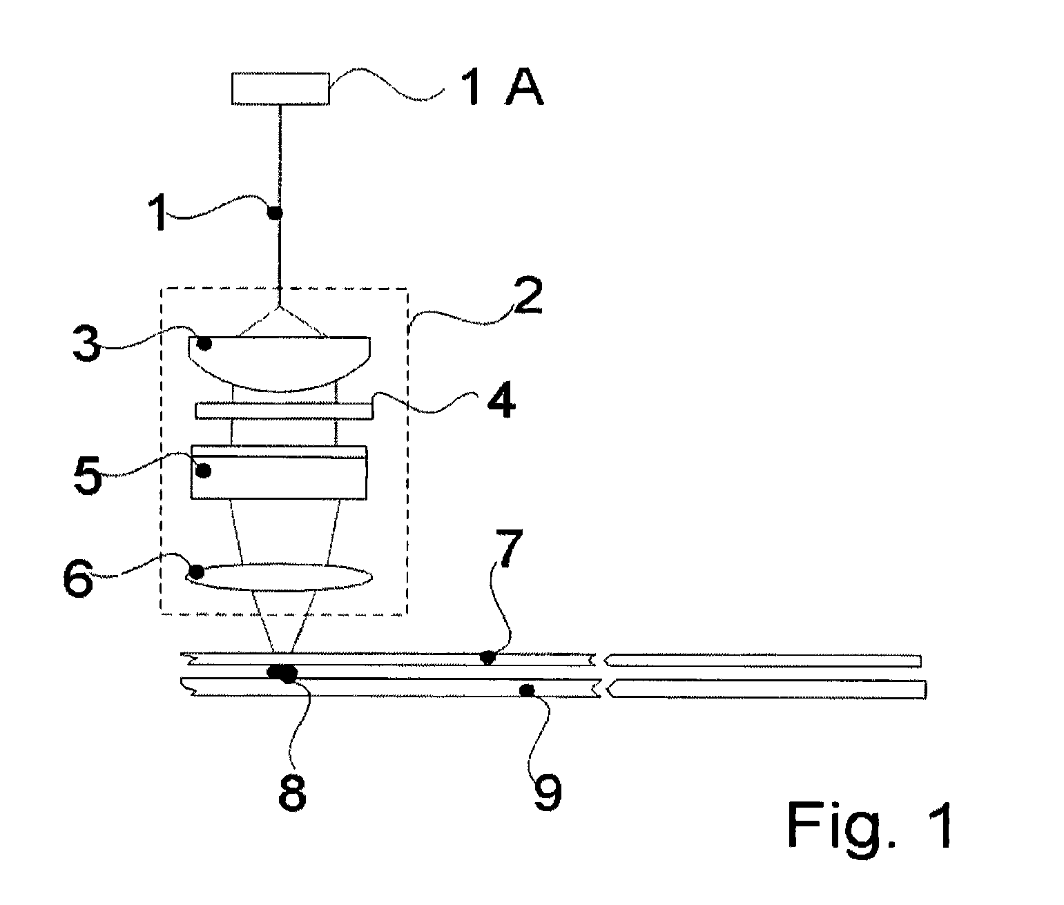
[0035]In accordance with the teachings of the present invention a method and apparatus for sealing an OLED is presented. In one embodiment a method and apparatus for dynamically shaping a laser beam onto a frit pattern is presented. The method and apparatus enables dynamic shaping of a laser beam and dynamic changes to characteristics of the laser beam in real-time during the laser sealing process. As such, variations in the frit pattern may be accommodated and a better hermetic seal may be achieved.

[0036]In one embodiment, a beam shaper is implemented using a plurality of optical lenses (i.e., optical system) that are selected or are adjusted relative to each other to dynamically shape a laser beam in real-time during the sealing process. In another embodiment, a diffuser is positioned within the optical system and the combination of the optical lenses and the diffuser are selected and / or adjusted to dynamically shape a laser beam footprint (i.e., beam size and shape) and dynamical...


PUM

PropertyMeasurementUnit
aspect ratioaaaaaaaaaa

Abstract

A beam shaper is implemented to seal an OLED. The beam shaper comprises a first and second lens and a beam shaper. Changing the relative position of the first, second lens and beam shaper relative to each other enables the beam shaper to generate laser beams with different shapes and intensity profiles.

Description

BACKGROUND OF THE INVENTION[0001]1. Field of the Invention[0002]The present invention is directed to sealing Organic Light Emitting Diodes (OLEDs) and displays made of OLEDs.[0003]2. Technical Background[0004]As a result of the many potential applications for compact and efficient displays, organic light-emitting diodes (OLEDs) are the focus of a tremendous amount of attention. OLEDs include electrodes and organic layers. There are two types of electrodes an anode and a cathode. There are also two types of organic layers a conducting layer and an emissive layer. In conventional implementations, the OLED components are deployed on a first substrate. The first substrate is typically made of clear plastic, glass, or foil. A second substrate that is made of similar material is used to cover the OLED. The first substrate and the second substrate are hermetically sealed with a frit, encasing the OLED in a package (i.e., glass package).[0005]During operations, the anode and the cathode (i....

Claims


Application Information

Patent Timeline
21 Aug 2012
Publication
US8247730B2
IPC
B23K26/00; C03B7/00; G02B5/02; H01J9/26
CPC
H01L51/5237; B23K26/08; B23K26/206; B23K26/324; B23K2103/54; B23K2101/36; H10K50/8426; H05B33/04
Inventors
LIU, ANPING; ZHANG, LU