Output ratio adjusting method for optic sensor

a technology of output ratio and optic sensor, which is applied in the direction of optical radiation measurement, instruments, spectrometry/spectrophotometry/monochromators, etc., can solve the problems of increased cost and complicated and achieve cost saving and simplified design and use of power amplification circuits.

Active Publication Date: 2012-08-21
TYNTEK
View PDF5 Cites 24 Cited by
  • Summary
  • Abstract
  • Description
  • Claims
  • Application Information

AI Technical Summary

Benefits of technology

[0005]An objective of the present invention is to provide a novel method for adjusting output ratio of an optic sensor, which provide outputs of light current of identical proportions or any desired ratio in accordance with response spectrum, optic response ratio, and light reception area ratio, so as to provide the efficacy of simplifying the design and use of a power amplification circuit and making it possible to use only one integrated circuit chip for cost saving.

Problems solved by technology

The conventional way of design is simple, but due to the fact that light current ratio becomes 18:23:16, the conventional devices suffer the drawbacks that the design and use of a power amplification circuit are made complicated and that, even worse, more integrated circuit chips are required in order to meet the specified requirements, leading to increased costs.

Method used


Image

  • Output ratio adjusting method for optic sensor
  • Output ratio adjusting method for optic sensor
  • Output ratio adjusting method for optic sensor

Examples


first embodiment

[0018]The output ratio adjusting method provided in accordance with the first embodiment for an optic sensor will be described first. The optic sensor used here is a sensor for detecting R, G, and B primary colors. The adjusting method comprises the following steps:

[0019](1) Setting the ratio among areas of R, G, B colors to 1:1:1, wherein the optic sensor can be a silicon (Si) made light detective diode (light detective diode of first material);

[0020](2) Obtaining an original ratio among light currents for R, G, B, which is set to X:Y:Z, for the area ratio of R, G, B being 1:1:1;

[0021](3) Obtaining a new ratio among light currents for R, G, B that is 1:1:1; and

[0022](4) Calculating a new ratio among areas of R, G, B, which is 1:X / Y:X / Z, for the new R, G, B light current ratio of 1:1:1.

[0023]For an example where the original R, G, B light current ratio is 16:23:18 under the condition that the R, G, B area ratio is 1:1:1, when the new R, G, B light current ratio is set to 1:1:1, the ...

second embodiment

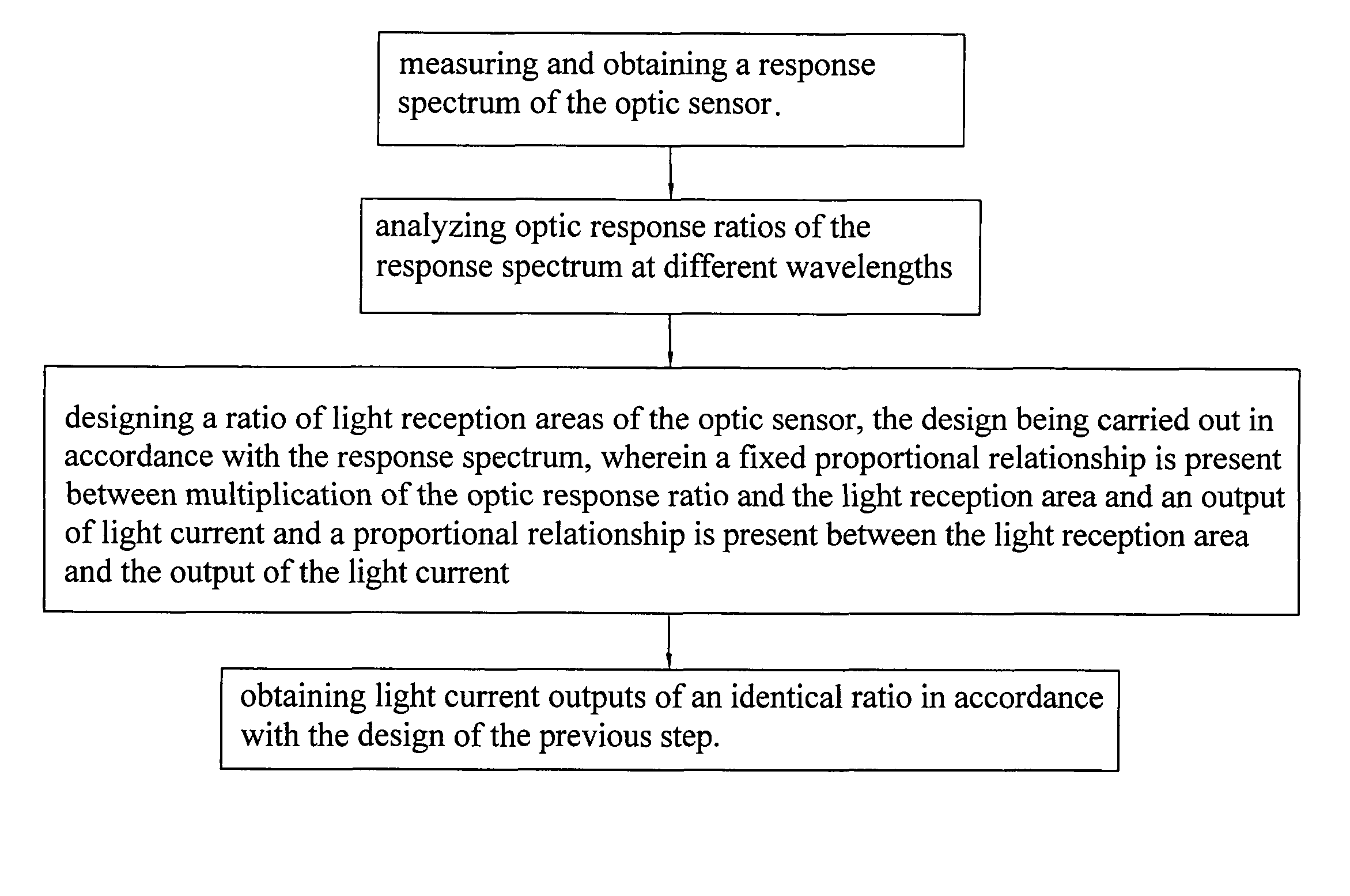
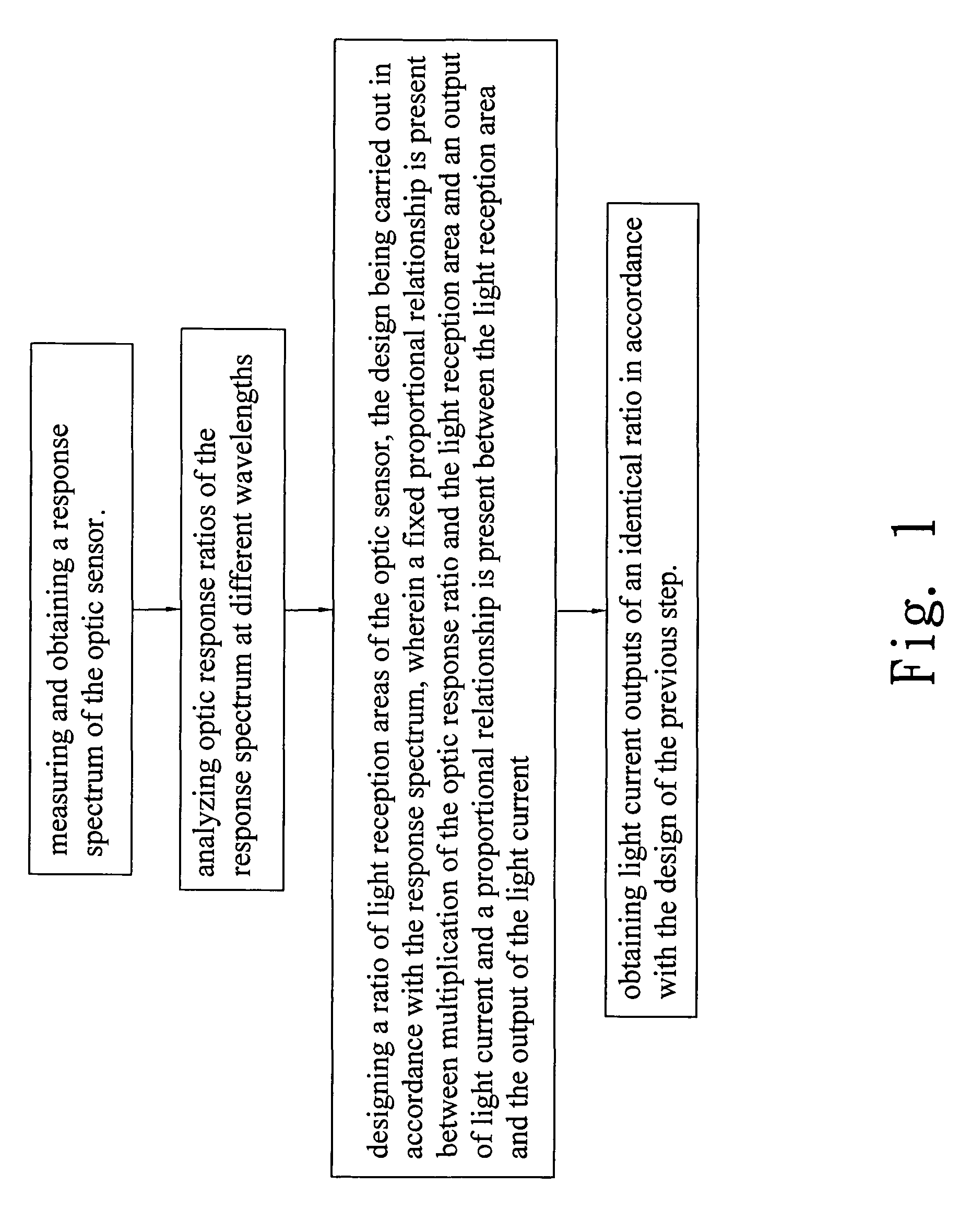
[0024]Referring to FIGS. 1-5, an output ratio adjusting method in accordance with the present invention for an optic sensor will be described. The optic sensor is a sensor for detecting various wavelengths. The adjusting method comprises the following steps:

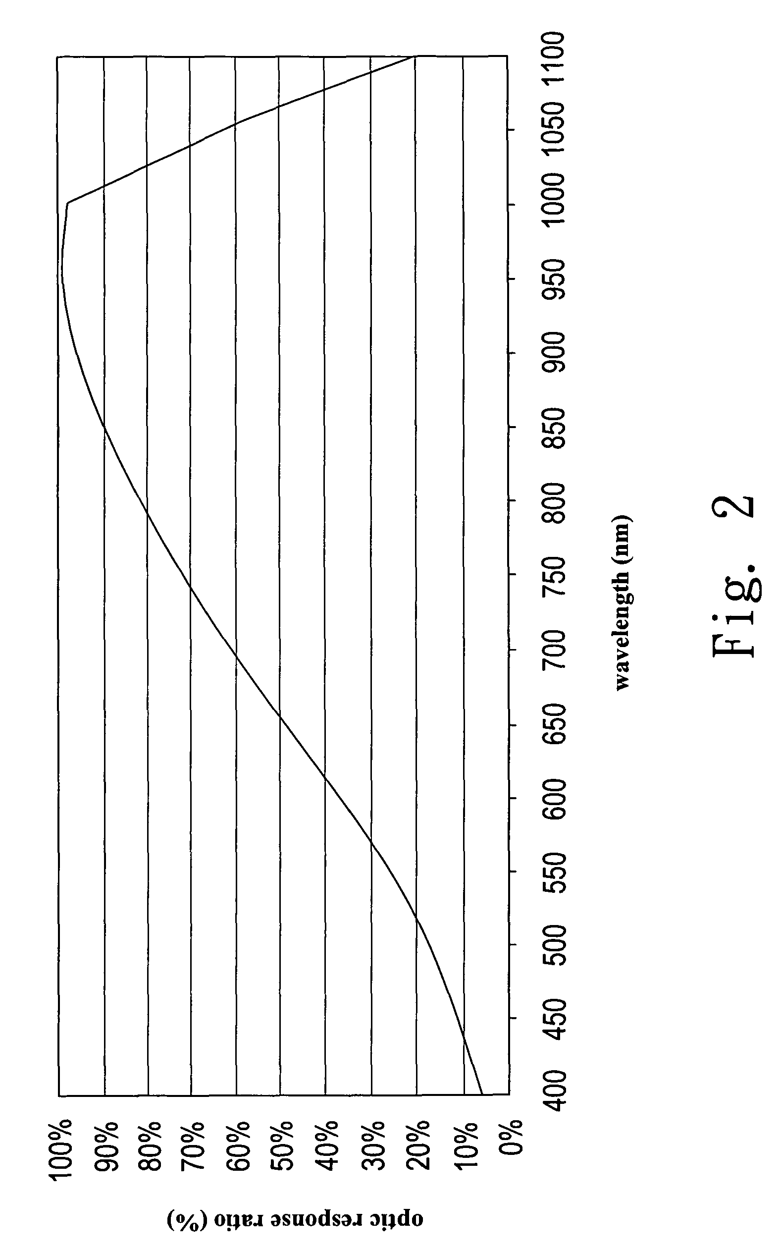
[0025](1) Measuring and obtaining a response spectrum (as shown in FIG. 2) for the optic sensor, wherein the optic sensor can be a silicon (Si) made light detective diode (light detective diode of first material), and wherein the axis of abscissa indicates wavelength;

[0026](2) Analyzing optic response ratios of the response spectrum at different wavelengths (see FIG. 3), wherein in the example illustrated, the optic response ratios obtained through the analysis are as follows: the optic response ratio being 6% for wavelength of 400 nm (nanometers); the optic response ratio being 11% for wavelength of 450 nm; . . . ; the optic response ratio being 99% for wavelength of 950 nm; the optic response ratio being 98% for wavelength of 1...

third embodiment

[0029]Referring to FIGS. 6-9, an output ratio adjusting method in accordance with the present invention for an optic sensor will be described. The optic sensor is a sensor for detecting various wavelengths. The adjusting method comprises the following steps:

[0030](1) Measuring and obtaining a response spectrum (as shown in FIG. 6, wherein the axis of abscissa indicates wavelength) for the optic sensor, wherein the optic sensor is a light detective sensor made of GaP, GaAsP, GaAs, InP, InGaAs, AlGaInP, or InGaN (light detective diode of second material), the light detective diode of the second material (or even including the light detective diode of the first material) belonging to ultraviolet (UV) enhance type, infrared (IR) enhance type, blue enhance type, or UV+blue enhance type;

[0031](2) Analyzing optic response ratios of the response spectrum at different wavelengths (as illustrated in FIG. 7), wherein in the example illustrated, the optic response ratios obtained through the an...


PUM


Abstract

A method for adjusting output ratio of an optic sensor includes the following steps: measuring and obtaining a response spectrum of the optic sensor; analyzing optic response ratios of the response spectrum at different wavelengths; designing a ratio of light reception areas of the optic sensor, the design being carried out in accordance with three aspects of “the response spectrum”“a fixed proportional relationship being present between multiplication of the optic response ratio and the light reception area and an output of light current” and “a proportional relationship being present between the light reception area and the output of the light current”; and obtaining light current outputs of identical proportions (such as 1:1:1) or in a desired ratio (meaning any arbitrary ratio other than 1:1:1, such as 1:2:1, 1:2:3, or 3:4:5) in accordance with the design of the previous step.

Description

FIELD OF THE INVENTION[0001]The present invention relates to a method for adjusting output ratio of an optic sensor, and in particular to a method for adjusting light current output ratio to identical proportions (1:1:1) or a desired ratio (any ratio other than 1:1:1) in accordance with response spectrum, optic response ratio, and light reception area ratio.BACKGROUND OF THE INVENTION[0002]The design of a conventional optic sensor is quite simple, where area ratio for the three primary colors, red (R), green (G), and blue (B), is set to 1:1:1. (For example, three elements respectively for R, G, and B all occupy an angular range of 120 degrees of a circle, thereby having identical area.) Under the condition that the area ratio is 1:1:1, for a conventional device that the present inventor acquired, the ratio of light current is 18:23:16.[0003]The conventional way of design is simple, but due to the fact that light current ratio becomes 18:23:16, the conventional devices suffer the dra...

Claims


Application Information

Patent Timeline
Patent Type & Authority Patents(United States)
IPC IPC(8): G01J5/02
CPCG01J1/02G01J1/0295G01J1/4228G01J1/429G01J3/2803G01J3/51G01J3/513
Inventor CHOU, WEN-LONGCHU, NI-TING
Owner TYNTEK
Why Eureka
Try Eureka